F.FWD
PAUSE
STILL
REW
CHANNEL
TAPE SPEED
POWER
VIDEO
AUDIO
VCR/TV
POWER
VCR/TV
TAPE IN
TIMER
REC
PLAY
STOP/EJECT
REC
OTR
MENU
F.FWD
PAUSE
STILL
REW
CHANNEL
TAPE SPEED
POWER
VIDEO
L AUDIO R
VCR/TV
POWER
VCR/TV
TAPE IN
TIMER
REC
PLAY
STOP/EJECT
REC
OTR
MENU
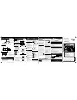
SERVICE MANUAL
Sec. 1: Main Section
I
Specifications
I
Preparation for Servicing
I
Adjustment Procedures
I
Schematic Diagrams
I
CBA’s
Sec. 2: Deck Mechanism Section
I
Standard Maintenance
I
Alignment for Mechanism
I
Disassembly/Assembly of Mechanism
I
Alignment Procedures of Mechanism
Sec. 3: Exploded views
and Parts List Section
I
Exploded views
I
Parts List
EWV401B
EWV601B
VIDEO CASSETTE RECORDER