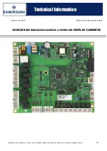
background image


Proprietary and confidential 

– Do not copy or distribute without permission from Emerson Climate Technologies GmbH 

1/42


    Technical Information 


Revision: Feb. 2019 


OEM Solutions Development & Sales 


ECB-D20

 REFRIGERATION CONTROL SYSTEM FOR 

DISPLAY


CABINETS 


Summary of Contents for ECB-D20

Page 1: ...ntial Do not copy or distribute without permission from Emerson Climate Technologies GmbH 1 42 Technical Information Revision Feb 2019 OEM Solutions Development Sales ECB D20 REFRIGERATION CONTROL SYSTEM FOR DISPLAY CABINETS ...

Page 2: ...ost synchronization 16 4 5 2 Configurable digital inputs 16 4 5 2 1 Lighting controls Day Night operation 16 4 5 2 2 Bus alarm 16 4 5 2 3 Door input 16 4 5 2 4 Standby mode 16 4 6 External Devices Modbus Master 17 4 6 1 1 Emerson ED3 Drive 18 4 6 1 2 Carlo Gavazzi Soft starter 18 4 6 1 3 EBM ESM Fan 18 5 Functions and parameters 19 5 1 Parameter list description 19 6 Display unit functions ECD D05...

Page 3: ... 8 Sensor positions 13 Figure 9 EXV Connection 14 Figure 10 EXM EXL 246 Windings 14 Figure 11 DIP switch 16 Figure 12 Internal Modbus Wiring 17 Figure 13 Fixed speed control 19 Figure 14 Variable speed control 19 Figure 15 Fix speed control 20 Figure 16 Variable speed control 20 Figure 17 Shift of Defrost Interval s by ModBus Address 22 Figure 18 Demand Defrost Detection 25 Figure 19 Deadband Cont...

Page 4: ...DIP switch has been set accordingly 2 1 Installation and wiring All connectors are provided with coding in o rder to prevent incorrect wiring Connect the sensors to the corresponding connectors Insert the cable of the expansion valve if present into the corresponding connector Connect the pressure switches for low pressure and high pressure Important The pressure switches must not have been trippe...

Page 5: ...ultiple refrigeration units the automatic defrost synchronization function can be handled using a hardware link or an external monitoring system The condensing pressure and or temperature can be controlled using a three way valve in case of water cooling or a fan control system in case of air cooling The controller is equipped with a day night program so that different setpoint values can be enter...

Page 6: ...3 common 4 normally open Stocko 036 Relay 8 5 common 6 normally open Stocko 054 Safety relay 7 common 8 normally open J21 RAST5 2 pin multipoint connector High pressure switch 1 24 V DC 2 input Stocko 002 J22 RAST5 2 pin multipoint connector Low pressure switch 1 J21 2 2 input Stocko 002 J23 RAST5 2 pin multipoint connector Digital input 1 1 input 2 input Stocko 037 Lumberg Kxx J24 RAST5 2 pin mul...

Page 7: ...t ECD 05 1 12V DC 2 open 3 GND Stocko 005 J26 RAST2 5 3 pin socket connectors 24 V 0 5 A power supply 1 24V DC 2 open 3 GND Stocko 007 J30 JST B6B Electronic expansion valve EXV 1 24V DC red 2 24V DC brown 3 coil 1 blue 4 coil 1 orange 5 coil 2 yellow 6 coil 2 white J25 RAST5 2 pin multipoint connector Synchronized defrost 1 8V DC 2 GNDIS Stocko 050 J27 RAST5 2 pin multipoint connector RS485 commu...

Page 8: ...ed in front of each relay to indicate the relay status The LED illuminates when a relay is energized Relay activated Modbus activity Master Slave Display ECD 05 Short circuit proof output future use EXV Synchronized defrost Modbus Master COM future use Modbus Slave COM Modbus Slave COM Safety Relay Relay 8 Relay 7 Relay 6 Relay 5 Relay 4 Relay 3 Relay 2 Relay 1 Alarm relay Power supply Disch P Suc...

Page 9: ... relay closed closed on on closed closed open on off open open closed off off open open open off off open Table 2 Logic safety chain 4 1 4 Alarm relay The alarm relay operates in a fail safe mode If no alarm is triggered the relay is activated and the LED is illuminated 4 2 Modbus communication All configuration on the controller is done via Modbus Monitoring System If the controller is connected ...

Page 10: ...ization When building up a Modbus communication with several boards it is beneficial to terminate the bus at the last board in line with a resistor This is done by placing a jumper on the board The pin connectors are located close to the RJ 45 terminals In some cases disturbances on the bus it could be also helpful to polarize the bus with two additional jumpers at one controller on the bus Figure...

Page 11: ...idential Do not copy or distribute without permission from Emerson Climate Technologies GmbH 11 42 Technical Information A principle setup where to place the termination jumper is shown in Figure 5 Figure 6 Bus termination ...

Page 12: ...rson temperature display module is supported ECD 05 An Emerson specific short circuit proof 1 bit bus is used as the transmission protocol 4 3 3 Digital inputs Two digital inputs are provided on RAST 5 connector strips J23 J24 The digital inputs are active inputs and can be powered by 24 V to 230 V AC DC Coding on the individual connectors ensures that they can only be connected to their matching ...

Page 13: ...perate with a 4 to 20 mA signal Every pressure sensor input has its own 24 V DC power supply and is limited to max 25 mA As temperature sensors 10K 25 C NTC sensors are used The supply voltage for the NTC sensors is 3 3V DC Figure 8 Sensor positions S1 Suction gas sensor S2 Air in sensor S3 Air out sensor S4 Fin sensor defrost sensor S5 Refrigeration unit temperature S6 Discharge temperature S4 S2...

Page 14: ...nologies GmbH 14 42 Technical Information 4 3 6 Electronic Expansion Valve EXV The controller module has an output for a unipolar electronic expansion valve Emerson EXM L which is controlled by a stepper motor Figure 9 EXV Connection yellow brown blue Figure 10 EXM EXL 246 Windings white red orange M ...

Page 15: ...trategy is to set the address via the DIP switches Configuration via DIP switches The first 6 DIP switches 1 6 are used to set up a binary Address Function DIP switch number 1 2 3 4 5 6 7 8 Modbus address 1 to 63 0 is not permitted x x x x x x Table 3 Modbus DIP switches Modbus Address 1 2 3 4 5 6 Modbus Address 1 2 3 4 5 6 1 On 33 On On 2 On 34 On On 3 On On 35 On On On 4 On 36 On On 5 On On 37 O...

Page 16: ...ols Day Night operation Without any activation the cabinet lighting is off and the night blinds are closed Lighting can be turned on and the night blinds can be opened using an external contact or Modbus command 4 5 2 2 Bus alarm This input is used as an external alarm This function is currently used as a gas alarm In case of a gas alarm the hybrid fan will be switched on only relevant for air coo...

Page 17: ...rity and one stop bit To run external devices it is necessary to set a unique Modbus address but equal Baud rate Stop bit and parity configuration in the proprietary configuration procedure of each device After that the devices can connected to the bus The address of each device must be set in the configuration of the ECB D10 By the next reset of the board automatically all devices are configured ...

Page 18: ...starters can be connected to the Modbus master interface The Modbus address must be set in the configuration A Modbus address of 0 means that the soft starter is not available The Carlo Gavazzi soft starter allows to switch the compressor via Modbus command and get a feedback of the compressor status To use CG soft starters the compressor command type must be set to soft starters At start up the c...

Page 19: ... on Set point Difference Control Temperature Figure 13 Fixed speed control Variable speed compressor The temperature control is done by a PI controller This parameter defines the temperature set point which is the middle of the P band The cut off temperature compressor off is this parameter minus of the day temperature difference 57 Day temperature difference In case of a sensor failure the PI con...

Page 20: ...For variable speed applications it is recommended to use a wider band 5K to prevent cut offs after defrost The cut off band of the temperature difference is not influencing the accuracy of PI temperature control It is only relevant in case the losses of the cabinet are lower than the cooling capacity at minimum speed In this case a freezing of the goods is prevented 0 Set point 1 2 Difference 1 2 ...

Page 21: ...lay period has expired 11 High superheat alarm setpoint If the superheat temperature rises above the configured value an alarm is triggered This may happen in case of a lack of refrigerant a valve that is too small No subcooling This function is only active if an electronic expansion valve is used 12 High superheat alarm delay If the temperature stays above the alarm level configured in 11 for a p...

Page 22: ... defined by this parameter the alarm will be triggered 22 Cabinet temperature alarm enabled If a cabinet temperature sensor is used high temperature and low temperature alarms for the cabinet can be activated 23 Low cabinet temperature alarm threshold Minimum permissible cabinet temperature When this value is reached refrigeration is stopped and will only be start again after the temperature has r...

Page 23: ...ation In any case the defrost is stopped and drain time is starting 32 when this time has elapsed 32 Defrost drain time Delay after a defrost phase During this period the water droplets can be drain off the evaporator When an electric defrost system is used the heater is turned off In case of a hot gas defrost system the compressor is stopped and the four way valve is switched The delay is used to...

Page 24: ...d on the display unit 48 Unit conversion The units used for calculating temperature and pressure can be changed SI and Imperial modes are available When SI is selected C and bar units will be used for the displayed values Also on the display unit the temperature is displayed in C When Imperial is selected F and psi units will be used for also displayed values Also on the display unit the temperatu...

Page 25: ... Detection 53 Demand defrost absolute delta threshold If in configuration parameter 78 Defrost mode a defrost mode with demand detection is selected this demand is detected in three stages As a second stage a detection is triggered if the absolute temperature difference between Air Out and Air In drops below the value configured in this parameter If this fails the defrost is triggered by time 26 D...

Page 26: ...geover from daytime to nighttime operation the fans and the compressor are switched off for this period This is necessary to guarantee a failure free shut down of the night curtain 60 Thermostat cycle off time In case of a temperature sensor failure the controller is entering an emergency operation mode cycling without a feedback The off time between two periods of cooling is defined by this param...

Page 27: ...ode a timeout is forcing the device back into normal mode after the time configured in this parameter 70 71 Pressure sensor type Several pressure sensor types can be selected 72 77 Temperature sensor type Several temperature sensor types can be selected 78 Defrost mode Four different ways of doing a defrost are configurable Value Defrost mode Defrost relais in use Fans Compressor 0 natural no on o...

Page 28: ...irst run on the speed defined by this parameter 86 Pack remove capacity delay If a pack controller is used stopping the next compressor reduce power could be delayed by this parameter 87 Pack add capacity delay If a pack controller is used starting the next compressor increase power could be delayed by this parameter 88 Pack compressor selection Two modes could be selected for pack control rotatin...

Page 29: ...dding of compressors is delayed by this parameter 91 Pack control mode The control strategy of the pack controller is configured by this parameter Two control strategies are available Dead band Figure 23 Pack Controller Dead Band Mode Percentage Figure 24 Pack Controller Percentage Mode 93 Maximum cooling time When this time has elapsed a stop of cooling is forced 94 Compressor minimum on time The...

Page 30: ...us Address of EBM Modbus fan 1 6 113 Modbus Address of Emerson ED3 Drive 115 120 Default speed of EBM Modbus fan 1 6 In normal operation the variable speed fans are running at this speed 121 Compressor command type The compressors can be controlled by the defined relays parameter 125 132 Relay use up to 3 compressors are available Or they can be switched by the softstarters definition of Modbus ad...

Page 31: ...9 Light relay 10 Solenoid relay 11 Defrost relay 12 Drive fan Table 6 Relay Functions 133 Digital input Night 134 Digital input bus alarm The digital inputs can be dedicated to different functions by parameter 133 134 155 Currently the function which can be dedicated are night input bus alarm door contact standby switch Also the input can be set as not connected Wert Digital Eingang 0 Not connecte...

Page 32: ...ng an oil return the Compressor is running with speed configured in parameter 148 Oil return speed for a time set by this parameter 151 Oil return threshold duration The time the compressor is running with a speed below the value configured in parameter 149 Oil return threshold is accumulated When the compressor speed rises above the threshold the duration timer is paused If the speed drops again ...

Page 33: ...5 Number of fin sensors It is possible to increase the number of fin sensors to optimize the defrost termination by fin temperature multiple measurement points or use a multi evaporator design By default the system is working with one fin sensor If two fin sensors are selected the second fin sensor is physically replacing the discharge temperature sensor A discharge temperature protection cannot b...

Page 34: ...ressor speed setup in Parameter 177 Hotgas Defrost compressor speed see Figure 26 Hotgas defrost sequence with without 4way Valve switching Figure 26 Hotgas defrost sequence with without 4way Valve switching 181 Digital input fans only The corresponding digital input DI 1 or DI 2 for the fans only mode can be set by this parameter 6 Display unit functions ECD D05 06 Lighting daytime operation Nigh...

Page 35: ...etup of Modbus communication 4 dt Detection of defrosting termination Baud rate Parity stop bits Value Meaning 0 9600 Baud s 1 19200 Baud s 2 38400 Baud s Value Meaning 0 No parity 2 stop bits 1 Even parity 1 stop bit 2 Odd parity 1 stop bit 3 No parity 1 stop bit 6 2 Configuration using display unit Press for 5 seconds When a 0 is displayed use the or buttons to enter password 27 factory setting ...

Page 36: ...0 x 12 month 1 x 31 day 1 300 Current time h x 60 min x 20 sec 3 Reading parameters 522 Current date year 2000 x 12 month 1 x 31 day 1 523 Current time h x 60 min x 20 sec 3 8 Defrost 8 1 Defrost controls The defrost method natural electric or hot gas can be configured by 78 defrost mode parameter 8 2 Defrost sequence The defrost process generally consists of 4 phases Preliminary phase Defrost is ...

Page 37: ...on dt configuration parameter If the mode is set to temperature or time the defrost cycle is stopped as soon as the configured temperature rises above the corresponding value of the predefined 28 Defrost limit temperature daytime operation or 29 Defrost limit temperature nighttime operation configuration parameter In any case the defrost cycle is stopped after a delay that is entered in the 30 Def...

Page 38: ...y a supervisor system The synchronization mode can be setup using Parameter 33 Defrost synchronize mode Hardware connection All cabinets in one defrost group are physically connected using a two wire connection on the Synchronized defrost connector J25 1 bit BUS logic As a fall back strategy a maximum waiting time for releasing the bus by all group members is respected Parameter 82 Sync Delay afte...

Page 39: ...0 no function Hardware alarm E10 12 0x0800 Low battery voltage Hardware alarm E11 13 0x1000 Class B software Hardware alarm Cooling stop E12 14 0x2000 EEPROM Hardware alarm Cooling stop E13 15 0x4000 Modbus Master Jam Hardware alarm E14 16 0x8000 Door Open Hardware alarm 17 0x0001 Low pressure Software alarm Cooling stop only active when using low pressure transmitter E32 18 0x0002 Low superheat S...

Page 40: ...ow battery voltage The battery is tested after power cycling the board and afterwards every 6 hours under load for a short period Software Class B critical The software has a safety integrated design For this purpose cyclical tests are performed that may lead to this error Refrigeration operation is interrupted when this error occurs EEPROM critical The EEPROM is used to save the configuration par...

Page 41: ...arm is only considered when an EXV is present This alarm is triggered when the valve is opened 100 for more than 10 min This may indicate a lack of refrigerant in the system High condensing pressure critical This alarm is only considered when the high pressure sensor is available This alarm is triggered when the condensing pressure remains above the threshold configured in the parameter 20 High co...

Page 42: ...V DC electrically isolated Outputs Safety relay 230V 10 A resistive 3 A inductive cos φ 0 5 Relay 1 230V 10 A resistive 3 A inductive cos φ 0 5 Relay 2 230V 10 A resistive 3 A inductive cos φ 0 5 Relay 3 230V 10 A resistive 3 A inductive cos φ 0 5 Relay 4 230V 10 A resistive 3 A inductive cos φ 0 5 Relay 5 230V 10 A resistive 3 A inductive cos φ 0 5 Relay 6 230V 10 A resistive 3 A inductive cos φ ...

Reviews: