background image

Instruction Manual 

Document: CI-CW-GFC-ISTRAN 
Part: D301647X012 
November, 2009 


www.EmersonProcess.com/Remote 

Remote Automation Solutions

ControlWave


GFC IStran


ControlWave GFC IStran 

Intrinsically Safe Communication Interface 


Summary of Contents for ControlWave GFC IStran

Page 1: ...n Manual Document CI CW GFC ISTRAN Part D301647X012 November 2009 www EmersonProcess com Remote Remote Automation Solutions ControlWave GFC IStran ControlWave GFC IStran Intrinsically Safe Communication Interface ...

Page 2: ...turning any equipment to RAS for repairs or evaluation please note the following The party sending such materials is responsible to ensure that the materials returned to RAS are clean to safe levels as such levels are defined and or determined by applicable federal state and or local law regulations or codes Such party agrees to indemnify RAS and save RAS harmless from any liability or damage whic...

Page 3: ...to your operation Emerson offers a full schedule of classes conducted by full time professional instructors Classes are offered throughout the year at various locations By participating in our training your personnel can learn how to install calibrate configure program and maintain your Emerson products and realize the full potential of your system For information or to enroll in any class go to h...

Page 4: ...BLANK PAGE ...

Page 5: ...dous Interface for Switched Mode 2 6 2 2 2 Configuring the Hazardous Interface for Unswitched Mode 2 6 2 2 3 Configuring the Non Hazardous Interface for Switched Mode 2 6 2 2 4 Configuring the Non Hazardous Interface for Unswitched Mode 2 6 2 3 Non Hazardous Power Output 2 6 Chapter 3 System Wiring 3 1 3 1 Introduction to System Wiring 3 1 3 2 Grounding 3 1 3 3 Cable Length 3 2 3 4 Field Wiring Di...

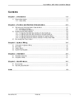
Page 6: ...ControlWave GFC IStran Instruction Manual vi Contents Issued Nov 09 ...

Page 7: ... or when the CW GFC IS receives external power through the IStran The IStran performs the following functions Replaces six intrinsic safety barriers for RS 232 signals 3 in 3 out Provides 500V isolation between two devices Operates at speeds up to 19 200bps Allows the CW GFC IS to receive power from outside the Division 1 area Allows the CW GFC IS to control power to a radio or modem located outsi...

Page 8: ...ch depth See Figure 1 2 1 3 and 1 4 The IStran assembly consists of the following major components One IStran printed circuit board PCB for the IStran assembly Yellow alodined aluminum base plate 0 060 inch thick Black anodized cover 0 090 inch thick Figure 1 2 Physical Dimensions IStran Front View Figure 1 3 Physical Dimensions IStran Edge Side View 1 2 Introduction Issued Nov 09 ...

Page 9: ...gure each interface independently to operate in either switched or unswitched mode Switched Mode Switched mode sets the TX drivers into a high impedance state to reduce power consumption Unswitched Mode In unswitched mode the TX drivers are always active and they always follow the corresponding RX inputs In cases where power consumption is not a key factor configure the IStran for unswitched mode ...

Page 10: ...ControlWave GFC IS Communication Interface Manual CI CW GFC ISTRAN 1 4 Introduction Issued Nov 09 ...

Page 11: ...imum 16 VDC RX Input Low Level Minimum 16 VDC Maximum 0 5 VDC RX Input Load Resistance Typical 3 01 Kohm TX Output Load Resistance Minimum 3 Kohm Quiescent Supply Current Both if in switched mode all TX off Maximum 800 uA Idle Supply Current Both if in unswitched mode all TX low Typical 21 mA Active Supply Current Both if active worst case Maximum 43 mA 2 1 1 Hazardous Interface You connect the ha...

Page 12: ...ce Characteristics Description Specification HPOUT Voltage Typical 6 3 VDC No Load Minimum 5 9 VDC Max Load Maximum 6 4 VDC No Load HPOUT Current Limit Threshold Minimum 130 mA at 8 VDC Maximum 300 mA at 16 VDC HPOUT Load Capacitance Maximum 100 uF HPIN Quiescent Supply Current Switched Mode Transmitters Off Maximum 100 uA HPIN Supply Current All TX Outputs High 3 KW Load Maximum 6 mA HTX Output H...

Page 13: ...ous interface Table 2 4 Non Hazardous Interface Connector Position Name Function NJ3 1 NPOUT Switched Power Output NJ3 2 NGND Local Ground reference Return for NPOUT NJ2 1 NPIN Power Supply Input NJ2 2 NGND Local Ground Return for NPIN NJ1 1 NTX1 Signal Output Follows HRX1 NJ1 2 NTX2 Signal Output Follows HRX2 NJ1 3 NTX3 Signal Output Follows HRX3 NJ1 4 NRX1 Signal Input NJ1 5 NRX2 Signal Input NJ...

Page 14: ... KWLoads Maximum 37 mA NPOUT Leakage Typical 1 uA Maximum 100 uA NPIN to NPOUT On Resistance NPIN 12 V Typical 0 3 ohm Maximum 0 5 ohm NRX3 to NPOUT On Typical 10 uS NPOUT Load Current Maximum 1 8 A Continuous Maximum 3 0 A Intermittent Max 60 Seconds 50 duty NTX Output High Level Typical 7 4 VDC into 3 Kohm Load Minimum 5 0 VDC Maximum 9 5 VDC NTX Output Low Level Typical 4 9 VDC into 3 Kohm Load...

Page 15: ...vices may not properly interpret the high impedance signal and in some systems it is impractical for you to operate either or both interfaces in switched mode In these cases or when power consumption is not a concern configure the interface s for unswitched mode In unswitched mode the TX drivers are always active and they always follow the corresponding RX inputs You enable or disable switched mod...

Page 16: ...ponding NRX inputs 2 2 3 Configuring the Non Hazardous Interface for Switched Mode To configure the non hazardous interface for switched mode place the supplied shorting jumper in the NJP1 position marked SW short NJP1 pins 1 and 2 as shown in Figure 2 2 The non hazardous interface is also in switched mode by default if you don t install a jumper at NJP1 When you configure the non hazardous interf...

Page 17: ... by the NPIN to NPOUT on resistance You must also take into account the resistance of the associated field wiring when you calculate the total drop between the power supply and the load In order to minimize resistance between NPIN and NPOUT the IStran does not provide over current You must install a fuse or other means of over current protection at the power source to prevent damage to the IStran ...

Page 18: ...ControlWave GFC IS Communication Interface Manual CI CW GFC ISTRAN 2 8 Function and Electrical Characteristics Issued Nov 09 ...

Page 19: ...ces To power both IStran interfaces using a single power source connect the power source between NPIN and NGND Use connector HJ2 see Figure 1 4 as a jumper position to wire HPOUT to HPIN and HGND to CGND Note that CGND and NGND are internally connected and that CGND is connected to the IStran case Refer to the field wiring diagrams in Section 3 4 for systems with a single power source When a groun...

Page 20: ...st not exceed 25 feet 3 4 Field Wiring Diagrams Figure 3 1 illustrates a typical communication system The power source to the non hazardous interface must not use or generate more than 250V If you install the IStran in a Division 2 area you must make power input and output connections using Division 2 wiring methods described in Section 4 1 In this example a single power source supplies both the c...

Page 21: ... power source to the non hazardous interface must not generate more than 16Vdc and must be able to supply at least 8Vdc If you install the IStran in a Division 2 area you must connect the power inputs and outputs using Division 2 wiring methods See Section 4 1 Note If you only require a modem or radio refer to Figure 3 1 and Figure 3 2 The only difference is that you can replace the 12V battery by...

Page 22: ...ControlWave GFC IS Communication Interface Manual CI CW GFC ISTRAN Figure 3 4 CW GFC IS with External Power Supply 3 4 System Wiring Issued Nov 09 ...

Page 23: ... of the IStran units The four mounting holes slots are 0 156 in diameter Total height is approximately 1 The case material is 5052 aluminum with a black anodize finish The thickness of the base is 0 060 and the top is 0 090 The case hardware is stainless steel The IStran accepts stranded wires up to 14AWG When you must insert two wires in a single position 18AWG is the maximum recommended size The...

Page 24: ...t must still maintain a 2 separation with either the IStran non hazardous interface wiring or any other circuits except those on the IStran hazardous interface Refer to Figures 3 1 through 3 4 in Chapter 3 when you connect wires between an optional modem or radio and an IStran assembly Note MDS and Freewave radios use different RXD TXD naming conventions MDS uses RXD and TXD to mean receive input ...

Page 25: ...ormerly IEEE 472 for surge withstand capability Vibration Effect 10 to 500 Hz at 1 g on any axis per SAMA PMC 31 1 without damage or impairment ESD Susceptibility Field connected circuits designed to meet the requirements of IEC 801 2 for ESD withstand capability up to 10KV EMI Compatibility Designed to meet the susceptibility requirements of IEC 801 3 level 2 3V M from 500kHz to 500MHz Designed t...

Page 26: ...ControlWave GFC IS Communication Interface Manual CI CW GFC ISTRAN 5 2 Specifications Issued Nov 09 ...

Page 27: ...nties which extend beyond the description of the face hereof F No agent of RAS is authorized to assume any liability for it or to make any written or oral warranties beyond those set forth herein REMEDIES A Buyer s sole remedy for breach of any warranty is limited exclusively to repair or replacement without cost to Buyer of any goods or parts found by Seller to be defective if Buyer notifies RAS ...

Page 28: ...RAS Web site www emersonprocess com remote and sending it via E Mail to CustServe RAS Emerson com A RAS Repair Dept representative will return E Mail or other requested method with a RA number C Mail Mail the form GBU 13 01 to Remote Automation Solutions A Division of Emerson Process Management Repair Dept 1100 Buckingham Street Watertown CT 06795 A RAS Repair Dept representative will return call ...

Page 29: ...____________ Phone _____________________ Fax ______________________ E Mail ______________________ Part II Please complete Parts II III for each unit returned Model No Part No _________________________ Description __________________________________ Range Calibration _________________________ S N ___________________________________ Reason for return Failure Upgrade Verify Operation Other ___________...

Page 30: ...BLANK PAGE ...
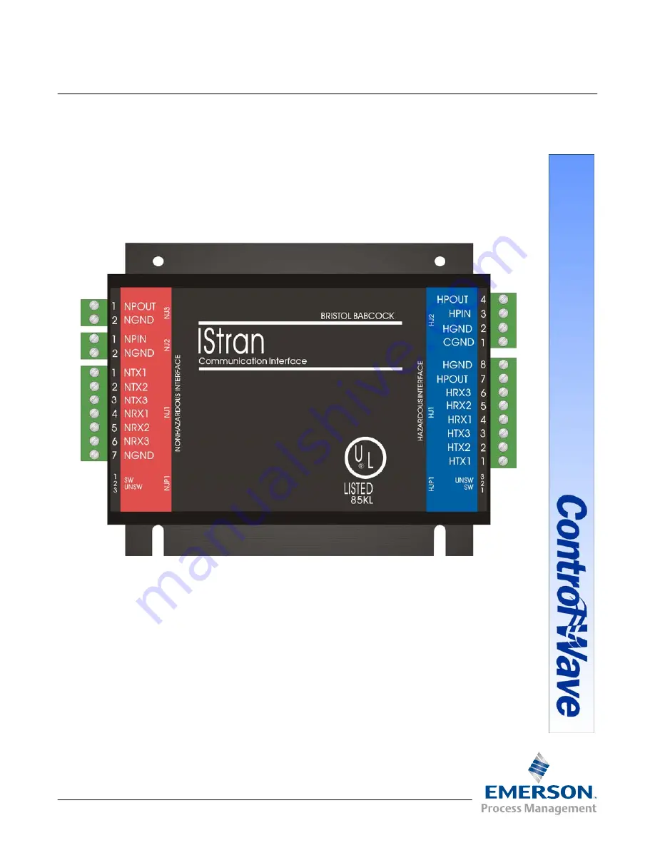
Page 31: ...dous characteristics 2 1 Hazardous interface configuring for Switched Mode 2 6 N Non Hazardous characteristics 2 1 Non Hazardous power output 2 6 S Specifications 5 1 Switched Mode 1 3 2 5 configuring the Hazardous interface for 2 6 configuring the non Hazardous interface for 2 6 T Tables 2 1 Common Characteristics for Hazardous and Non Hazardous Interfaces 2 1 2 2 Hazardous Interface Connector 2 ...

Page 32: ... WITH RESPECT TO THIS MANUAL AND IN NO EVENT SHALL RAS BE LIABLE FOR ANY INCIDENTAL PUNITIVE SPECIAL OR CONSEQUENTIAL DAMAGES INCLUDING BUT NOT LIMITED TO LOSS OF PRODUCTION LOSS OF PROFITS LOSS OF REVENUE OR USE AND COSTS INCURRED INCLUDING WITHOUT LIMITATION FOR CAPITAL FUEL AND POWER AND CLAIMS OF THIRD PARTIES Bristol Inc Bristol Babcock Ltd Bristol Canada BBI SA de CV and the Flow Computer Di...

Reviews: