


Questions, problems, missing parts: Before returning to the store call
Emerson Electric Customer Service - 8 a.m. - 6 p.m., Eastern, Monday-Friday
Part No. F40BP72580009 Form No. BP7258-9
Revision: 150605 U.L. Model No.: 42-ANT & 52-ANT
www.emersonfans.com
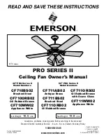
CF710BS02
Brushed Steel
CF710ORB02
Oil Rubbed Bronze
CF710WW02
Appliance White
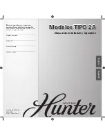
42” PRO Series II
Model Numbers
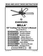
CF711AB02
Antique Brass
CF711BS02
Brushed Steel
CF711ORB02
Oil Rubbed Bronze
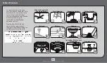
50” PRO Series II
Model Numbers
Net Weight:
16.5
Lbs.
Net Weight:
19.8
Lbs.
READ AND SAVE THESE INSTRUCTIONS
1-800-654-3545
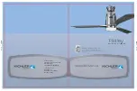
PRO SERIES II
Ceiling Fan Owner's Manual
CF711ORS02
Oil Rubbed Bronze
with Scavo Glass
CF711WW02
Appliance White
CF711 shown
• Español - página 25
• Français - page 49