


Part No. F40BP72580008
Form No. BP7258-8
U.L. Model No.: 42-ANT/52-ANT
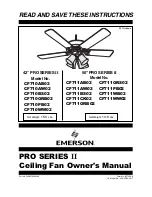
READ AND SAVE THESE INSTRUCTIONS
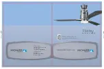
PRO SERIES
II
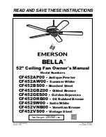
Ceiling Fan Owner's Manual
Net Weight:
19.8
Lbs.
Net Weight:
15.0
Lbs.
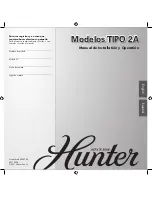
50” PRO SERIES
II
Model No.
CF711AB02
CF711ORS02
CF711AW02
CF711PB02
CF711BS02
CF711WB02
CF711CK02
CF711WW02
CF711ORB02
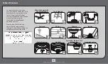
42” PRO SERIES
II
Model No.
CF710AB02
CF710AW02
CF710BS02
CF710ORB02
CF710PB02
CF710WW02
CF711 shown