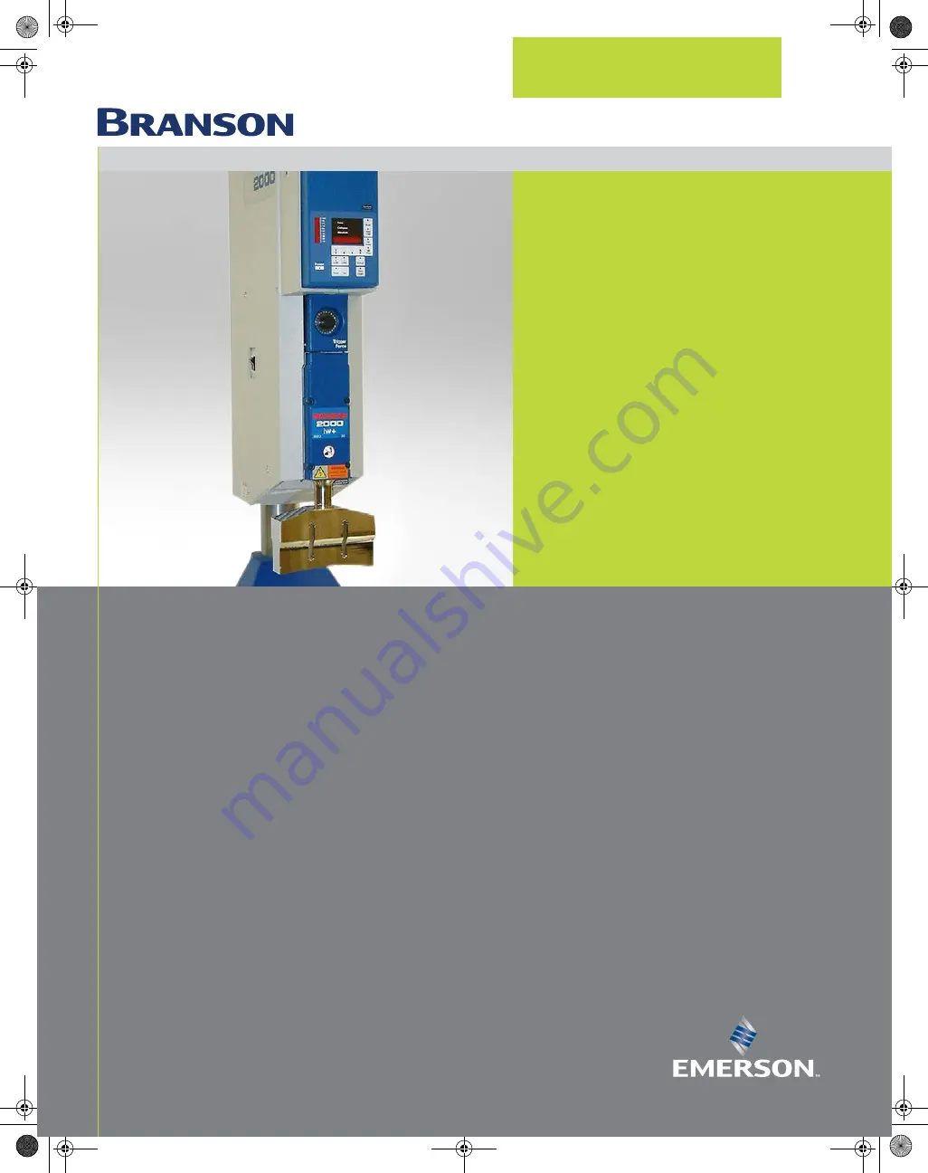
background image

2000IW/IW+

Integrated Welder

Branson Ultrasonics Corporation

41 Eagle Road

Danbury, CT 06813-1961 USA

(203) 796-0400

http://www.bransonultrasonics.com

100-214-251 - REV. 05

I n s t r u c t i o n   M a n u a l

100-214-251 IWoper.book  Page i  Friday, June 16, 2017  4:12 PM

Summary of Contents for Branson 2000 Series

Page 1: ... Welder Branson Ultrasonics Corporation 41 Eagle Road Danbury CT 06813 1961 USA 203 796 0400 http www bransonultrasonics com 100 214 251 REV 05 Inst ruction Manual 100 214 251 IWoper book Page i Friday June 16 2017 4 12 PM ...

Page 2: ...ocumentation at its next revision and printing Therefore when requesting service assistance for specific units note the Revision information found on the cover of this document and refer to the printing date which appears at the bottom of this page Copyright and Trademark Notice Copyright 2003 Branson Ultrasonics Corporation All rights reserved Contents of this publication may not be reproduced in...

Page 3: ...e kept with the equipment Thank you for choosing Branson Introduction This manual is arranged into several structured chapters which will help you find the information you may need to know to safely handle install set up program operate and or maintain this product Please refer to the Table Of Contents and or the Index of this manual to find the information you may be looking for In the event you ...

Page 4: ...lation and Setup 4 1 About Installation 40 4 2 Handling and Unpacking 41 4 3 Take Inventory of Small Parts 44 4 4 Installation Requirements 45 4 5 Installation Steps 49 4 6 Accessory Input Output Option 60 4 7 Guards and Safety Equipment 61 4 8 Assemble the Acoustic Stack 62 4 9 Installing the Ultrasonic Stack in the Integrated Welder 65 4 10 Adjusting Welder Height and Aligning the Horn 67 4 11 A...

Page 5: ...ic Test 108 6 8 Horn Down 109 6 9 Converter Cooling 110 Chapter 7 Maintenance 7 1 IW IW Preventive Maintenance 112 7 2 Parts Lists 116 7 3 Circuits 117 7 4 Troubleshooting 118 100 214 251 IWoper book Page iv Friday June 16 2017 4 12 PM ...

Page 6: ...als IW IW 54 Figure 4 10 Operating Cycle Timing Table 2000IW 55 Figure 4 11 Operating Cycle Timing Table 2000IW 55 Figure 4 12 Moving Jumpers 56 Figure 4 13 International Harmonized Line Cord Color Code 56 Figure 4 14 Type 1 DIP Switch Marked OPEN on Top of Switch Default Settings 57 Figure 4 15 Type 2 DIP Switch Marked ON on face of Switch Default Settings 58 Figure 4 16 Accessory Input Output Co...

Page 7: ... 7 1 Reconditioning Stack Surfaces 114 Figure 7 2 Disassembly of Air Filter Components 114 Figure 7 3 2000 IW IW Interconnect Schematic 117 Figure 7 4 Manual Adjustment Procedure Flowchart 119 100 214 251 IWoper book Page vi Friday June 16 2017 4 12 PM ...

Page 8: ...ing the Type 2 Switch Select Block 58 Table 4 7 Assemble the Acoustic Stack 62 Table 4 8 Tools 63 Table 4 9 Stud Torque Values 64 Table 4 10 Tip to Horn Torque value 64 Chapter 5 Technical Specifications Table 5 1 Environmental Specifications 76 Table 5 2 Electrical Requirements 76 Table 5 3 2000IW IW Boosters 78 Table 5 4 Other items used with the 2000IW IW 79 Chapter 6 Operation Table 6 1 Parame...

Page 9: ...viii 100 214 251 REV 05 100 214 251 IWoper book Page viii Friday June 16 2017 4 12 PM ...

Page 10: ...Safety Requirements and Warnings 2 1 2 General Precautions 4 1 3 Warranty Statement Disclaimer 6 1 4 How to Contact Branson 8 1 5 Returning Equipment for Repair 9 1 6 Obtaining Replacement Parts 12 100 214 251 IWoper book Page 1 Friday June 16 2017 4 12 PM ...

Page 11: ...hroughout this manual warrant special attention WARNING General Warning Warning indicates a hazardous situation or practice that if not avoided can result in serious injury or death CAUTION General Warning Caution indicates a hazardous situation which if not avoided could result in minor or moderate injury NOTICE Notice is used to address practices not related to personal injury It contains import...

Page 12: ...ert the user to items of concern or hazard The following warning symbols appear on the 2000IW IW Integrated Welder Figure 1 1 Safety Labels on the 2000IW IW Integrated Welder Figure 1 2 Safety Label on Left Door of the 2000IW IW Integrated Welder 100 214 251 IWoper book Page 3 Friday June 16 2017 4 12 PM ...

Page 13: ... is not installed When using larger horns avoid situations where fingers could be pinched between the horn and the fixture Be aware that the Integrated Welder is armed if air pressure is indicated on the front panel air pressure gauge 1 2 1 Intended Use of the System The 2000 Series Integrated Welder houses all the components of an ultrasonic welding system These are designed for a wide variety of...

Page 14: ...Safety Color Code ANSI Z535 3 Criteria for Safety Symbols ANSI Z535 4 Product Safety Signs and Labels BS EN ISO 12100 1 2 Safety of Machinery Basic concepts general guidelines for design EN 55011 Limits and methods of measurement of radio disturbance of industrial scientific and medical radio frequency equipment EN 60204 1 Safety of Machinery Electrical Equipment of machines EN 60529 Degrees of pr...

Page 15: ...rom defects in material and workmanship for a period of time specified in Table 1 1 Warranty Period from the date of invoice The warranty does not apply to Any product which has been subject to misuse misapplication neglect including without limitation inadequate maintenance accident or improper installation modification or adjustment Applications requiring metal to metal contact when the ultrason...

Page 16: ...tomer is responsible for all shipping charges Additional Warranty Notes Components replaced during in warranty repair carries the remainder of the original warranty Serialized assemblies replaced during the repair of out of warranty equipment are warranted for a period of 12 months Travel charges for Branson service personnel will be waived on service calls performed within 30 days of invoice date...

Page 17: ...rn telephone number 3 Have your manual with you If troubleshooting a problem refer to Chapter 7 Maintenance 4 Know your equipment model and serial numbers found on a gray data label on the units Information about the Horn part number gain etc or other tooling may be etched into the tooling Software or firmware based systems may provide a BOS or software version number which may be required 5 What ...

Page 18: ..._________ If you are returning equipment to Branson please call the Danbury Repair Department to obtain a Returned Goods Authorization RGA number At your request the Repair Department will fax an RGA form to fill out and return with the equipment 1 5 2 Record information about the Problem Before sending equipment for repair record the following information and send a copy of it with the equipment ...

Page 19: ...in Table 1 2 Branson Contact below My Local Branson Representative s name is _______________________________________________________________________ I can reach this representative at _______________________________________________________________________ Table 1 2 Branson Contact What you need help with or information about Whom to Call At this Extension Information about new welding systems or c...

Page 20: ...ons as well as inside the carton along with the reason for return Make a list of all components packed in the box KEEP YOUR MANUAL 2 Return general repairs by any convenient method Send priority repairs by air freight Prepay the transportation charges FOB the repair site NOTICE Items that are sent Freight Collect will be refused 100 214 251 IWoper book Page 11 Friday June 16 2017 4 12 PM ...

Page 21: ... A parts list is found in Chapter 7 Maintenance of this manual listing descriptions and EDP part numbers If you need replacement parts coordinate the following with your purchasing agent Purchase order number Ship to information Bill to information Shipping instructions air freight truck etc Any special instructions for example Hold at the airport and call Be sure to give a name and phone number C...

Page 22: ...s Covered 14 2 2 Overview of these Models 15 2 3 Compatibility with Branson Products 18 2 4 Features 19 2 5 Front Panel Controls 20 2 6 Rear Panel 27 2 7 System Inputs Outputs 29 2 8 Glossary of Terms 31 100 214 251 IWoper book Page 13 Friday June 16 2017 4 12 PM ...

Page 23: ...odels Covered This manual contains instructions for installing setting up and operating a 2000IW and 2000IW Series Integrated Welders for 1100 2200 and 3300 Watt output 100 214 251 IWoper book Page 14 Friday June 16 2017 4 12 PM ...

Page 24: ...plications welders can contain a base assembly with 2 Palm Buttons and an Emergency Stop knob For Automated applications welders can contain a hub in place of the base assembly A typical setup will be with a standard 40 inch column 4 5 and 6 foot lengths are also available An enclosure housing the carriage and slide system the pneumatic system the power supply and the Control Module The Control Mo...

Page 25: ...ensates for changes in horn frequency if necessary These changes may occur due to increased temperatures wear on the horn face or material buildup on the horn 2 2 4 System Control Module The System Control Module consists of a Controller Board and a Keyboard Display board It controls the power supply module and the welder s pneumatic functions The keyboard display board allows the user to change w...

Page 26: ...ON and EXTERNAL RESET signals are available through 24V DC interface on the back panel of the welder In addition a READY signal is available as both 24V DC and isolated contact closure Using this interface selected faults or weld errors sensed by the welder can be communicated outside the welder for monitoring cycles and sorting suspect workpieces 2 2 8 Dynamic Triggering and Follow Through Many w...

Page 27: ...on Products The 2000IW IW Series Integrated Welders are compatible for use with either a standard base or a hub for automation The CJ20 converter is used for the 1100 2200 and 3300 Watt units 100 214 251 IWoper book Page 18 Friday June 16 2017 4 12 PM ...

Page 28: ...o that you can determine correct values for settings Horn Down Mode A manual procedure used to verify system setup and alignment Limits A class of user definable process alarms that alert you if a part falls into a range that you classified as reject parts Memory When Memory is turned on weld parameters at the end of the cycle will be entered Membrane Keyboard For high reliability and immunity fro...

Page 29: ...der dual calibrated at 0 100 psig o 700 kPa 2 Pressure Regulator Adjusts amount of air pressure applied to cylinder range of 5 100 psig 35 700 kPa Pull to set push to lock 3 Down Speed Control Controls rate of carriage descent multi turn color coded each turn calibrated at 0 9 Pull red locking to set push locking ring to lock Return rate is fixed 100 214 251 IWoper book Page 20 Friday June 16 2017...

Page 30: ...ure calibrated 1 24 in half steps 48 detents corresponding to a force range of 15 200 lbs 67 890 N 8 Carriage Door Provides access to the converter booster horn stack secured by 4 captive hex screws 9 Mechanical Stop Locking Nut Locks the mechanical stop to desired depth 10 Mechanical Stop Limits the distance the carriage travels to prevent horn from contacting the fixture or nest when no workpiec...

Page 31: ...e At the end of the weld cycle it displays alarms 3 Up Down Switches Once you have selected weld parameters to change these four switches increase or decrease your selected parameters displayed in the NUMERIC DISPLAY From left to right these switches are referred to as the FAST DOWN switch the SLOW DOWN switch the SLOW UP switch and the FAST UP switch Pressing these switches will have no effect un...

Page 32: ...ng the switch again will de select HORN DOWN mode 8 AB Time Switch Selects the afterburst TIME parameter for modification when display lock is inactive displays the AB TIME parameter in the NUMERIC DISPLAY and lights the AB TIME switch LED 9 AB Delay Switch Selects the Afterburst DELAY parameter for modification when display lock is inactive displays the AB DELAY parameter in the NUMERIC DISPLAY a...

Page 33: ... Up Down Switches Once you have selected weld parameters to change these four switches increase or decrease your selected parameters displayed in the NUMERIC DISPLAY From left to right these switches are referred to as the FAST DOWN switch the SLOW DOWN SWITCH the SLOW UP switch and the FAST UP switch Pressing these switches will have no effect until you have selected parameters to change These sw...

Page 34: ...ile in the Horn Down mode will bring the carriage down without triggering ultrasonics Pressing the switch again will de select HORN DOWN mode 10 Actual Switch a 2000IW only feature Selects for display the actual value for the previous weld Each succeeding press will display the actual value of each of the three modes in turn displaying the actual time or actual distance and lighting the relevant M...

Page 35: ...e NOTICE In Collapse or Absolute Distance Modes the weld time parameter acts as an overriding condition Ensure Time is setup to allow for the collapse or absolute distances to be attained during a weld 15 Mode Indicator LEDS a 2000IW only feature Light once you have selected the mode you wish to alter indicate the mode selected Table 2 3 Front Panel Displays IW Item Name Function 100 214 251 IWope...

Page 36: ...tive kits see below Figure 2 5 Rear Panel Table 2 4 Rear Panel Item Name Function 1 Accessory Input Output An advanced feature that allows connection of Power Out Memory Seek Frequency Frequency Offset Power Supply Module Status Outputs Amplitude Output and Amplitude Control Input Requires Accessory Input Output kit 101 063 721 15 pin male connector 100 214 251 IWoper book Page 27 Friday June 16 2...

Page 37: ...signals are available In addition a READY signal is available as both 24V DC and isolated contact closure Using this connector selected faults or weld errors sensed by the welder can be communicated outside the welder for monitoring cycles and sorting suspect workpieces Connector 4 is a 25 pin female 5 Start Connector Connects the welder to its base or to customer supplied start signals Connector ...

Page 38: ...en activated will simulate pressing RESET refer to Figure 2 4 Front Panel Displays callout 5 IW 7 IW You cannot start a weld cycle if the EXTERNAL RESET line is active 2 7 3 READY Signal ALARM Connector The welder uses the Upper Limit Switch ULS input to determine when the carriage has started to descend and when it has reached its home position on its return at the end of the weld cycle The Contr...

Page 39: ... following situations an error will be generated The input becomes inactive while the welder is in the READY state The input does not become inactive within 4 seconds after the solenoid valves are activated The input becomes active before weld timing begins during a weld cycle The input does not become active within 4 seconds after the solenoid valves are deactivated 100 214 251 IWoper book Page 3...

Page 40: ...arm Beeper An audible signal that sounds when a general alarm has occurred Amplitude The peak to peak movement at the horn face Always expressed as a percentage of the maximum Amp Control The ability to set amplitude digitally or by an external control Automatic A pretrigger condition indicating that pretrigger engages when the actuator leaves the upper limit switch Beep An audible signal produced...

Page 41: ...e a cycle can be run The reset is accomplished by using the reset key on the front of the Integrated Welder or by external reset at the User I O Scrub Time The amount of time after detection of a ground condition option IW only to the termination of ultrasonics Seek A setting where ultrasonics are on at 5 amplitude for the purpose of finding the resonant frequency of the stack Stack Converter Boos...

Page 42: ...00 214 251 REV 05 33 Chapter 3 Delivery and Handling 3 1 Shipping and Handling 34 3 2 Receiving 35 3 3 Unpacking 36 3 4 Returning Equipment 37 100 214 251 IWoper book Page 33 Friday June 16 2017 4 12 PM ...

Page 43: ... environmental guidelines should be respected in the shipping of the Integrated Welder CAUTION General Warning The Integrated Welder internal components are sensitive to static discharge Many components can be harmed if the unit is dropped shipped under improper conditions or otherwise mishandled Table 3 1 Environmental Specifications Environment Range Storage Shipping Temperature 25 C to 55 C 13 ...

Page 44: ...se of a lifting device Table 3 2 Inspection upon delivery Step Action 1 Verify that all parts are complete according to the packing slip 2 Check the packing and the unit for damage visual inspection 3 Report any damage claims to your carrier immediately 4 Determine if any component has become loose during shipping and if necessary tighten screws NOTICE If the goods delivered have been damaged duri...

Page 45: ...eps Step Action 1 Unpack the Integrated Welder as soon as it arrives Save the packing material 2 Inspect the controls indicators and surface for signs of damage 3 Remove the cover of the Integrated Welder Table 7 2 Replacement Parts to check if any components became loose during shipping NOTICE If damage has occurred notify the shipping company immediately Retain packing materials for inspection 1...

Page 46: ...ase call your Customer Service Representative to receive approval to return goods to Danbury If you are returning equipment for repair refer to Chapter 1 Safety and Support Section 1 5 Returning Equipment for Repair of this manual for appropriate procedure 100 214 251 IWoper book Page 37 Friday June 16 2017 4 12 PM ...

Page 47: ...38 100 214 251 REV 05 100 214 251 IWoper book Page 38 Friday June 16 2017 4 12 PM ...

Page 48: ...49 4 6 Accessory Input Output Option 60 4 7 Guards and Safety Equipment 61 4 8 Assemble the Acoustic Stack 62 4 9 Installing the Ultrasonic Stack in the Integrated Welder 65 4 10 Adjusting Welder Height and Aligning the Horn 67 4 11 Adjusting the Mechanical Stop 68 4 12 Testing the Installation 72 4 13 Still Need Help or Parts Have Questions 73 100 214 251 IWoper book Page 39 Friday June 16 2017 4...

Page 49: ...ctionally ready to weld International safety labels are found on the 2000IW IW Integrated Welder Those that are of importance during installation of the system are identified in the figures in this and other chapters of the manuals CAUTION Heavy Object The Integrated Welder weighs 145 pounds Handling unpacking and installation can require help or the use of lifting platforms or hoists 100 214 251 ...

Page 50: ...and other components may be packed inside the shipping container depending on the equipment ordered Integrated Welders are shipped on a wooden pallet with a cardboard box cover over protective foam shells for support Heed the This End Up arrows and the Open Top First instructions The packaging is designed to be removed from the assemblies from an upright orientation only Figure 4 1 Unpacking the S...

Page 51: ...entory of Small Parts 4 2 2 Stand 2000IW IW on a Hub Figure 4 2 Unpacking the Stand 2000IW IW on a Hub Hub shown separately CAUTION General Warning The column and column support are under spring tension from the counterbalance spring Do NOT attempt to disassemble the column from the stand but always keep the column support clamped together When making height adjustments carefully and slowly releas...

Page 52: ...Carefully lay the stand on its right side NOT ON THE SIDE WITH THE LINEAR ENCODER 8 Remove the hub from the pallet and set it aside Some hubs are bolted to the pallet from the top 9 Unpack the converter booster cables manuals and toolkit that may be in the insert box Save the packing material including the blocks of wood 10 Go to Section 4 3 Take Inventory of Small Parts Figure 4 3 Ultrasonic Conv...

Page 53: ...Handle Wrench x x Mylar Washer Kit x 20kHz Spanners 2 x Fixture Bolts and Washer x M8 Allen Wrench x x Table 4 2 List of Cables P N Length For Start Stop control in automated machines 101 240 020 Start Cable J911 8 req PLA 101 240 015 Start Cable J911 15 req PLA 101 240 010 Start Cable J911 25 req PLA For Status Alarm interfacing to automated machines 101 240 021 Alarm Cable J971 8 ft 101 240 016 ...

Page 54: ...oaded and unloaded The internal power supply module must be accessible for user parameter changes and settings so considerations must be made to be able to access the DIP switches The Welder should be positioned so it does not draw in dust dirt or material via its internal fan Consideration should also be given to rear electrical and pneumatic connections approximately 6 in 150 mm Refer to the ill...

Page 55: ... Integrated Welder Dimensional Drawing 4 4 2 Environmental Specifications Table 4 3 Environmental Specifications Environmental Concern Acceptable Range Humidity 30 to 95 non condensing 100 214 251 IWoper book Page 46 Friday June 16 2017 4 12 PM ...

Page 56: ... Up to 1000 m IP Rating 2X Table 4 3 Environmental Specifications Environmental Concern Acceptable Range Table 4 4 Input Power Requirements 1100 W 100V 120V 13 Amp Max 100V 17 Amp CB NEMA 5 15P Plug 1100 W 200V 240V 6 5 Amp Max 200V 8 Amp CB None supplied 2200 W 200V 240V 14 Amp Max 200V 17 Amp CB None supplied 3300 W 200V 240V 21 Amp Max 200V 20 Amp CB None supplied CAUTION General Warning Synthe...

Page 57: ...to prevent impurities and moisture from entering through the air lines and damaging your equipment To facilitate this when installing your welder use an air line hookup that includes a riser and waterleg Refer to Figure 4 5 Hooking Up the Air Line Connect the air line to a clean 5 micron unlubricated dry compressed air supply 35 to 100 psi 240 to 690 kPa Use the supplied self draining air filter w...

Page 58: ...3 8 inch US bases or M10 metric bases Use flat washers against the metal casting to prevent gouging The use of nylon lock nuts with your cap screws is suggested to reduce loosening due to vibration and movement 3 Connect factory air to the air input on the rear of the Welder Use a lockout device on the air line if required 4 Verify the base start switch control cable is properly connected to the b...

Page 59: ...ounting bolt holes are provided at the corners of the casting and will accept your 3 8 inch or M10 hardware Use flat washers against the metal casting to prevent gouging Refer to Figure 4 8 Start Switch Connection Codes CAUTION General Warning The hub must be installed with its front in the same direction as the front of the welder The column bolts of the hub are found on the rear of the hub See F...

Page 60: ... connect to the Welder using the integral power cord See Table 4 4 Input Power Requirements for plug and receptacle requirements for your specific power level Refer to the unit s Model Data Tag to be sure of the power rating of the Model in your system Open the left side cover door of your welder and locate the Line Voltage Selector Jumper figure Line Voltage Selector Jumper The voltage select is ...

Page 61: ...cycle These must be closed within 200 milliseconds of each other or error message ER28 or ER29 will display This doesn t require a reset but for the next cycle switches must be within time limit to preclude re occurrence of error message Refer to Note above EMER STOP is an emergency stop switch normally closed The welder can also be started by an EXTERNAL START signal To do so connect a J911 cable...

Page 62: ...AL ALARM pin 18 READY signal pin 19 relay pins 9 and 10 and WELD ON pin 20 The SOLENOID OUTPUT provides a negative logic output when referenced to the 24V DC source pins 5 and 6 GENERAL ALARM READY AND WELD ON signals provide a negative logic output when reference to 24V RTN pins 21 22 and 23 These signals can be interfaced with a customer supplied device to monitor system status and trigger some ...

Page 63: ...onnected Pins 1 2 3 4 7 8 11 12 14 15 16 17 and 24 Note 2 Typical Circuitry for Pins 18 19 and 20 CAUTION General Warning Ensure all unused wires are properly isolated Failure to do so may result in power supply module or system failure 100 214 251 IWoper book Page 54 Friday June 16 2017 4 12 PM ...

Page 64: ...100 214 251 REV 05 55 Figure 4 10Operating Cycle Timing Table 2000IW Figure 4 11Operating Cycle Timing Table 2000IW 100 214 251 IWoper book Page 55 Friday June 16 2017 4 12 PM ...

Page 65: ...nductors found in the international harmonized line cord Add the plug that is appropriate for your input power receptacle Figure 4 13International Harmonized Line Cord Color Code LEFT SIDE COVER OPEN COLLECTOR 24V OPEN COLLECTOR 24V OPEN COLLECTOR 24V CAUTION General Warning The power supply module can be permanently damaged if it is connected to the incorrect line voltage or if the wiring connect...

Page 66: ...discharge When working inside the Integrated Welder use a grounded wrist strap and minimize your movement to reduce the possibility of damage due to static electricity WARNING General Warning Unplug the welder if previously connected and wait at least two 2 minutes before opening the case Hazardous Voltages exist and are stored in the system NOTICE Toggle 5 is not used Table 4 5 Options for Settin...

Page 67: ... Set for Fixed 100 Amplitude Variable turned Off 6 Down Off Start Short Sets ramp time to 10 ms 7 Down 8 Down Medium Sets ramp time to 35 ms 7 Up 8 Down Standard Sets ramp time to 80 ms 7 Down 8 Up Long Sets ramp time to 105 ms 7 Up 8 Up NOTICE Toggle 5 is not used Table 4 6 Options for Setting the Type 2 Switch Select Block Functions Options Set Toggle Seek Seek on power up Checks horn frequency ...

Page 68: ...at End of Weld Updates horn frequency memory at the end of each weld 4 Down Off 4 Up On Amplitude Control Set for Fixed 100 Amplitude Variable turned Off 6 Up On Start Short Sets ramp time to 10 ms 7 Down 8 Down Medium Sets ramp time to 35 ms 7 Up 8 Down Standard Sets ramp time to 80 ms 7 Down 8 Up Long Sets ramp time to 105 ms 7 Up 8 Up Table 4 6 Options for Setting the Type 2 Switch Select Block...

Page 69: ... the necessary hardware and instructions to retrofit the standard welder to utilize these features The external cable provided 101 241 360 in the kit is a 15 pin female to an open end When the new rear mounting plate provided in the kit is installed this cable will plug into the male 15 pin connector mounted topmost on this plate refer to Figure 2 5 Rear Panel The signals to the pinout are illustr...

Page 70: ...ton is reset If you are running automation you can use external reset that is connected to your User I O board Figure 4 17Integrated Welder Emergency Stop Button If you are using an Emergency Stop signal from the Start Switch cable you must clear the Emergency Stop condition before the System will operate Column Base Start Switch Start Switch Emergency Stop Button 100 214 251 IWoper book Page 61 F...

Page 71: ...the correct inside and outside diameters at each interface Table 4 7 Assemble the Acoustic Stack Step Action 1 Raise the welding head by loosening the upper and lower column clamps and turning the elevation knob clockwise After raising the head re tighten the column clamps 2 Open the carriage door by loosening the captive screws 3 Clean the mating surfaces of the converter booster and horn Remove ...

Page 72: ...er and the booster to the horn 8 Torque to 220 in lbs 24 85 Nm Table 4 8 Tools Tool EDP Number 20 kHz Torque Wrench 101 063 617 20 kHz Spanner Wrench 101 118 039 Table 4 7 Assemble the Acoustic Stack Step Action Booster Spanner provided Horn Vise Vise Jaw protectors aluminum or soft metal See Stack Assembly Procedure Converter 100 214 251 IWoper book Page 63 Friday June 16 2017 4 12 PM ...

Page 73: ...pecifications Figure 4 20Connecting Tip to Horn NOTICE The use of a Branson torque wrench or the equivalent is recommended P N 101 063 617 for 20kHz systems Table 4 9 Stud Torque Values Used On Stud Size Torque EDP 20 kHz 3 8 x 24 x 1 290 in lbs 33 Nm 100 098 120 20 kHz 3 8 x 24 x 1 1 4 290 in lbs 33 Nm 100 098 121 20 kHz 1 2 x 20 x 1 1 4 450 in lbs 50 84 Nm 100 098 370 20 kHz 1 2 x 20 x 1 1 2 450...

Page 74: ...he carriage Firmly push the stack into place with the acorn nut on the top of the converter making contact with the contactor in the top of the carriage 6 Reinstall the door assembly and start the four door screws 7 Align the horn by rotating it if necessary Torque the carriage door to 20 in lbs to secure the stack Figure 4 21Installing a 20kHz Stack in a Branson Welder WARNING General Warning To ...

Page 75: ...tional guard sometimes required with very large horns is shown for position only It extends several inches to either side of the base and prevents the user from operating the welder and pinching their fingers or hands between the base and the tooling CAUTION General Warning The base is cast metal and the mounting holes can become stripped if the hardware is overtightened Tighten your hardware only...

Page 76: ...s 4 Place the workpiece to be welded in the fixture 5 Set the pressure regulator to zero and manually lower the carriage until the horn contacts the workpiece 6 Loosen the carriage door screws and rotate the stack until the horn is properly aligned with the workpiece Tighten the carriage door screws 7 Adjust the air pressure to 15 psi 8 Use HORN DOWN to check the fixture s position Press HORN DOWN...

Page 77: ...efore contacting the stop turn the adjusting knob counterclockwise until the stop contacts the carriage 3 Recheck the clearance between the horn and the fixture and make any necessary re adjustments to the stop You can use Horn Down press HORN DOWN on the front panel to check this position while the welder is under pressure 4 When the desired setting is obtained tighten the locknut The locknut wil...

Page 78: ...e an insulated probe to alter DIP switch settings After altering a DIP switch close and secure the left side cover and plug in the power cord Figure 4 24DIP Switch Location WARNING General Warning Be sure the welder is electrically disconnected before opening the cover NOTICE These settings are different for the IW and the IW and read only at power up 100 214 251 IWoper book Page 69 Friday June 16...

Page 79: ...S input becoming inactive for more than 100 ms Level defines TRS lost as TRS input becoming inactive for more than 10 ms SW1 3 Timing on ULS This switch determines when weld timing will start When ON weld timing will be on the ULS Otherwise OFF default setting timing will be on the TRS when pretrigger ins enabled SW1 2 Not used SW1 1 Pretrigger on ULS When ON this switch allows ultrasonic energy t...

Page 80: ...ned as lost during Weld or Hold time Edge defines TRS lost as TRS input becoming inactive for more than 100 ms Level defines TRS lost as TRS input becoming inactive for more than 10 ms SW1 3 Timing on Pretrigger This switch determines when weld timing will start When ON weld timing starts when the ULS signal is inactive When OFF weld timing starts when the Trigger switch TRS is active This choice ...

Page 81: ...there are no alarm messages displayed go on to the next step 7 Fit a test part onto the fixture 8 Press the Horn Down key and then press and hold the two start switches The horn will descend to the fixture on the base of the Welder This verifies specifically that the pneumatic system is working 9 Press the Horn Down key again The horn will retract The system should now be functional and can be set...

Page 82: ...re here for you If you need assistance with your 2000 series system call your local Branson representative or contact Branson customer service by calling the appropriate department as indicated on Table 1 2 Branson Contact in Section 1 5 3 Departments to Contact 100 214 251 IWoper book Page 73 Friday June 16 2017 4 12 PM ...

Page 83: ...74 100 214 251 REV 05 100 214 251 IWoper book Page 74 Friday June 16 2017 4 12 PM ...

Page 84: ...100 214 251 REV 05 75 Chapter 5 Technical Specifications 5 1 Technical Specifications 76 100 214 251 IWoper book Page 75 Friday June 16 2017 4 12 PM ...

Page 85: ...should be installed approximately 3 feet off the floor The welder weighs approximately 145 pounds For physical dimensions refer to Figure 4 4 2000IW IW Integrated Welder Dimensional Drawing 5 1 2 Electrical Requirements 5 1 3 Pneumatic Requirements The factory compressed air supply must be clean to a 5 micron level dry and unlubricated air with a regulated maximum pressure of 100 psig 690 kPa Depe...

Page 86: ...trasonic signals from entering the AC main line System Control Board The System Control Board performs the following functions Responding to start and stop signals Responding to alarm and reset signals Responding to user input from the front panel Activating and monitoring ultrasonics Provides information for Front Panel Displays Generate alarms Control communications CAUTION General Warning Synth...

Page 87: ...nant frequency Control starting amplitude Provide overload protection for the Ultrasonic Power Module Store operating frequency of last weld frequency memory and use the stored frequency as a starting point for the next weld Check and update frequency memory on start up Provide switch selective starting ramp times Start DC Power Module The Switching DC Power Module rectifies filters and regulates ...

Page 88: ... 101 149 059 Booster Solid Mount 1 2 20 Input 1 2 20 Output Titanium 1 2 5 black 101 149 099 Titanium 2 1 silver 101 149 098 Titanium 1 1 5 gold 101 149 097 Titanium 1 1 green 101 149 096 Titanium 1 0 6 purple 101 149 095 Table 5 4 Other items used with the 2000IW IW Item Description P N Mylar Washers for 20 kHz systems Kit 10 each 1 2 in or 3 8 in 100 063 357 Kit 150 each 1 2 in 100 063 471 Kit 1...

Page 89: ...80 100 214 251 REV 05 100 214 251 IWoper book Page 80 Friday June 16 2017 4 12 PM ...

Page 90: ...e Parameters 92 6 3 Controlling the Front Panel Display 95 6 4 Setup Procedure 96 6 5 Weld Cycle State Displays and Alarms 100 6 6 Resetting the System 107 6 7 Ultrasonic Test 108 6 8 Horn Down 109 6 9 Converter Cooling 110 100 214 251 IWoper book Page 81 Friday June 16 2017 4 12 PM ...

Page 91: ...trolled from the front panel by adjusting Time Collapse and Absolute Distance parameters depending on the selected mode and if available in your WARNING General Warning When setting up and operating the welder observe the following precautions 1 High voltage is present Do not operate with covers open or removed 2 To prevent the possibility of electric shock make sure that the welder if properly gr...

Page 92: ... collapse includes distance travelled during Hold Time which depending on your application may increase the weld collapse distance Absolute Distance IW only Absolute Mode sets the amount of absolute distance travelled from ULS while ultrasonics were active Note that the actual absolute includes distance travelled Hold Time which depending on your application may increase or decrease the weld absol...

Page 93: ...riggering ultrasonic energy activates on the Upper Limit Switch ULS instead of the Trigger Switch TRS when DIP switch settings are altered Use pretriggering in certain applications such as staking when you need ultrasonics to start pretrigger before contacting the workpiece You can also use pretriggering for large or hard to start horns Pretriggering ultrasonics at the ULS is generally recommended...

Page 94: ...ctions describe how to use weld modes with their associated parameters 6 1 2 1Time Mode Use Time mode when consistency of welder cycle time is an important part of your operation For example use in automated systems where the welder cycle time must be limited to maintain overall system speed For IW only in Time mode the Time and Limits are active The Collapse and Absolute Limits act as safeties If...

Page 95: ... Disabled Safety Limits Alarm Weld Time Controls No No No Hold Time Controls No No No AB Delay Controls Yes No No AB Time Controls Yes No No Time Limit Monitors Yes Yes Yes Limit Monitors Yes Yes Yes Collapse Limit Monitors Yes Yes Yes Limit Monitors Yes No Yes Absolute 100 214 251 IWoper book Page 86 Friday June 16 2017 4 12 PM ...

Page 96: ... Limit Monitors Yes Yes Yes Limit Monitors Yes No Yes NOTICE Safety limits if reached will terminate Weld Time Table 6 4 Time Mode Parameters IW only Parameter Control and or Monitor Can be Disabled Safety Limits Alarm NOTICE In Collapse or Absolute Distance Modes the weld time parameter acts as an overriding condition Ensure Time is setup to allow for the collapse or absolute distances to be atta...

Page 97: ...or Can be Disabled Safety Limit Alarm Collapse Distance Controls No No No Hold Time Controls No No No AB Delay Controls Yes No No AB Time Controls Yes No No Time Limit Monitors Yes Yes Yes Limit Monitors Yes No Yes Collapse Limit Monitors Yes Yes Yes Limit Monitors Yes No Yes 100 214 251 IWoper book Page 88 Friday June 16 2017 4 12 PM ...

Page 98: ...tance limits The following figure illustrates weld cycles in Absolute Distance mode with different limit settings Absolute Limit Monitors Yes Yes Yes Limit Monitors Yes No Yes NOTICE Safety limits if reached will terminate Weld Time Table 6 5 Collapse Distance Mode Parameters IW only Parameter Control and or Monitor Can be Disabled Safety Limit Alarm NOTICE In Collapse or Absolute Distance Modes t...

Page 99: ...tor Can be Disabled Safety Limits Alarm Absolute Distance Controls No No No Hold Time Controls No No No AB Delay Controls Yes No No AB Time Controls Yes No No Time Limit Monitors Yes Yes Yes Limit Monitors Yes No Yes Collapse Limit Monitors Yes Yes Yes Limit Monitors Yes No Yes Absolute 100 214 251 IWoper book Page 90 Friday June 16 2017 4 12 PM ...

Page 100: ...Monitors Yes No Yes NOTICE Safety limits if reached will terminate Weld Time Table 6 6 Absolute Distance Mode Parameters IW only Parameter Control and or Monitor Can be Disabled Safety Limits Alarm 100 214 251 IWoper book Page 91 Friday June 16 2017 4 12 PM ...

Page 101: ...mn the left side figures indicate effects of pressing SLOW UP DOWN switches while the right side figures indicate effects of pressing FAST UP DOWN switches If you press an UP DOWN switch after pressing a parameter selection switch except MODE the next press of the parameter selection switch will set the parameter you selected to is original value Then the next press will set the parameter to its m...

Page 102: ...parameter to 25 of full scale for that parameter This option is not available for weld time collapse or absolute distance press four times to disable the parameter if the parameter can be disabled or to set the parameter to its minimum value if it cannot be disabled press five times to set the parameter to its minimum value if the parameter can be disabled These shortcuts are used to speed up navi...

Page 103: ... values 6 2 4 3Recalling cold start parameter values If you wish to return to the cold start factory set parameters as the welder is powered immediately after activating the welder simultaneously press and hold the FAST UP and the FAST DOWN switches Hold until the welder displays coldstrt IW or rdy IW until the mode is changed or until the welder is recycled NOTICE If a parameter can be disabled t...

Page 104: ...uations where the load is less than 50 Use Display Lock when you do not want operators to change settings However you can restore cold start parameter values with this setting For further information on setting these DIP switches refer to Section 4 11 1 Setting DIP Switches If these measures do not resolve your problem contact your local representative or Branson s Product Support Department 100 2...

Page 105: ...ate the start mechanism The weld cycle will start as follows a The horn advances and contacts the workpiece b Pressure develops between the horn and the workpiece activating the TRS NOTICE Push the E STOP button to terminate the cycle at any time This causes the carriage to retract and ultrasonic energy to shut off Twist the E STOP button to return the welder to READY NOTICE For 900 IW IW users wh...

Page 106: ...an be removed from the fixture 5 Weld a few workpieces using the initial parameters and check for desired properties You may not obtain optimum results initially but based on the quality of the weld obtained and the POWER BARGRAPH reading you can alter settings or adjust switches to achieve satisfactory results Change one setting at a time until a weld is produced in minimum time with maximum stre...

Page 107: ...98 100 214 251 REV 05 Figure 6 3 Setup and Operation in Time Mode 100 214 251 IWoper book Page 98 Friday June 16 2017 4 12 PM ...

Page 108: ...100 214 251 REV 05 99 Figure 6 4 Setup and Operation in Collapse Absolute Distance Modes 100 214 251 IWoper book Page 99 Friday June 16 2017 4 12 PM ...

Page 109: ...d below Table 6 9 2000IW State Displays State Description S0 One START SWITCH Pressed Wait for Second START SWITCH The currently active welding parameters are stored in NOVRAM non volatile memory and a 100 to 200 ms stagger timer is started during which time the other START SWITCH must be pressed or an alarm will be generated and the welder will return to READY state S1 Both START SWITCHES Pressed...

Page 110: ...or an alarm will be generated S7 Wait for ULS Active During the 4 sec end of sequence timer the ULS input must become active or an alarm will be generated S8 Wait for START SWITCHES During the 4 sec end of sequence timer the START SWITCH inputs must be released or an alarm will be generated Table 6 10 222IW State State Description S0 Ready State stores the current welding parameters into the NOVRA...

Page 111: ...trasonics until the weld parameter conditions have been met or any enabled plus limit is reached or the overload input from the SPM becomes active or the TRS input and one of the START SWITCH inputs are lost S12 Hold Time deactivates ultrasonics Remains active for the required amount of time or until TRS input is lost S13 AB Delay deactivates the SV drive circuits and waits for the AB Time to expi...

Page 112: ...weld timing began Error 08 x x TRS Enter Error Non Latching The TRS input did not become active within 4 sec of ULS becoming inactive Error 09 x LLS Enter Non Latching The LLS input became active before weld timing began Error 10 x PBS Enter Non Latching The START SWITCHES were not pressed within 100 to 200 ms of each other or the START SWITCH inputs were lost before the TRS input became active an...

Page 113: ...be cleared by RESET or by the external RESET input Error 23 x ULS Lost Waiting for TRS Latchable After the ULS input became inactive the ULS input became active again before the PTS input became active PTS enabled Error 24 x PTS Lost Waiting for TRS Latchable After the PTS input became active the PTS input became inactive again before the TRS input became active Error 25 x SV Deactive Error Non Re...

Page 114: ... Setup Error Latchable Value for minus limit greater than value for plus limit or minus limit greater than nominal value or plus limit less than the nominal value Error 34 x Collapse Limited Setup Error Latchable Value for minus limit greater than value for plus limit or plus limit less than nominal value Error 35 x Absolute Limit Setup Error Latchable Value for minus limit greater than value for ...

Page 115: ...e is started by START SWITCH or start cable or they will clear themselves after 1 5 seconds 6 5 2 2Non Resettable alarms Non Resettable alarms prevent the welder from cycling They are caused by hardware failure You must turn the welder OFF correct the situation and then turn the welder back on before you can start the next weld cycle These alarms cannot be cleared by pressing RESET or the EXTERNAL...

Page 116: ...FAST DOWN switches until the welder displays coldstart and goes to Time mode For the IW welders Press both the FAST UP and FAST DOWN switches until the welder displays RDY and goes to Time mode This will set Weld and Hold Time to 50 ms the minimum value and disable AB Delay AB Time and all limits This procedure also functions if you have activated Display Lock 100 214 251 IWoper book Page 107 Frid...

Page 117: ...ltrasonic energy will remain on as long as TEST remains pressed and the welder does not overload Pressing TEST causes the POWER BARGRAPH to switch to the DIP Switch selected multiplier for further information refer to Section 4 11 1 Setting DIP Switches After 4 to 6 seconds the Autotune feature is disabled and the welder enters manual tuning mode for further information refer to Section 7 4 1 Manu...

Page 118: ...N 2 Press the START SWITCHES simultaneously and hold until the TRS is active indicated by a single beep At this point you may release the START SWITCHES 3 To enter READY state and retract the horn press HORN DOWN again While you are in HORN DOWN the NUMERIC DISPLAY will indicate horn travel 100 214 251 IWoper book Page 109 Friday June 16 2017 4 12 PM ...

Page 119: ...mediately after substantial welder operation and without ultrasonics applied to the horn To check the temperature tape a pyrometer or similar temperature measuring device onto the front drive nose piece of the converter assembly Wait for the device to reach the temperature of the driver If this temperature is 120 F 48 C or higher your equipment requires additional cooling Contact Branson for furth...

Page 120: ...00 214 251 REV 05 111 Chapter 7 Maintenance 7 1 IW IW Preventive Maintenance 112 7 2 Parts Lists 116 7 3 Circuits 117 7 4 Troubleshooting 118 100 214 251 IWoper book Page 111 Friday June 16 2017 4 12 PM ...

Page 121: ...efficiently when the Converter Booster Horn Stack mating surfaces are flat in solid contact and free from fretting corrosion Poor contact between mating surfaces wastes power output makes tuning difficult increases noise and heat and may cause damage to the converter For standard 20 kHz products a Branson Mylar washer should be installed between the horn and booster and horn and converter Replace ...

Page 122: ...inst the emery cloth Figure 7 1 Reconditioning Stack Surfaces 7 Rotate the part 120 degrees placing your thumb over the spanner wrench hole and repeat the lapping procedure in step 6 8 Rotate the part another 120 degrees to the next spanner wrench hole and repeat the lapping procedure in step 6 9 Re examine the mating surface If necessary repeat steps 2 5 until you remove most of the contaminant R...

Page 123: ...e Air Filter is self draining If contaminants build up inside the Air Filter you can bleed the filter by turning the brass nut on the bottom If your Air Filter leaks or gets dirty follow the instructions below Figure 7 2 Disassembly of Air Filter Components 100 214 251 IWoper book Page 114 Friday June 16 2017 4 12 PM ...

Page 124: ...place the Air Filter 7 Clean the float and filter element 8 Reassemble the Air Filter as follows Place the float into the bowl Figure 7 2 Screw the filter element into the housing until finger tight Screw the bowl into the housing WARNING General Warning Turn air pressure to zero and disconnect the air line connection Failure to do this leaves the welder under potentially dangerous air pressure WA...

Page 125: ...l Supply 200 132 777 PC BD Line IW UPS 100 242 546 Kit Power Module 1 1 kW 2000 IW 101 063 719 Kit Power Module 2 2 kW 2000 IW 101 063 720 2000 IW IW Operators Manual 100 214 251 2000 IW IW Maintenance Manual 100 214 250 Kit Fan 101 063 722 Kit Accessory Input Output Connection 101 063 721 PCB Display IW 100 242 101 PCB Display IW 100 242 112 Kit Controller 2000 IW and IW 101 063 718 Kit Linear En...

Page 126: ...100 214 251 REV 05 117 7 3 Circuits Figure 7 3 2000 IW IW Interconnect Schematic 100 214 251 IWoper book Page 117 Friday June 16 2017 4 12 PM ...

Page 127: ...es not provide proper tuning using the following procedure Remove the Autotune label from the Front Panel NOTICE This should NOT be a regularly performed procedure but should be used only as a last resort CAUTION General Warning Do not force the potentiometer beyond its stop limits The total rotation from full cw to full ccw is only 270 100 214 251 IWoper book Page 118 Friday June 16 2017 4 12 PM ...

Page 128: ...100 214 251 REV 05 119 Figure 7 4 Manual Adjustment Procedure Flowchart 100 214 251 IWoper book Page 119 Friday June 16 2017 4 12 PM ...

Page 129: ...120 100 214 251 REV 05 100 214 251 IWoper book Page 120 Friday June 16 2017 4 12 PM ...

Page 130: ... to contact 8 Branson representative 73 C Cables 44 Carriage and Slide System 16 Circuit Descriptions 77 Clearing Weld Cycle Alarms 105 Column Clamps 42 43 Compatibility with Branson Products 18 Connect factory air 51 Connecting Tip to Horn 64 Converter Cooling 110 Converters and Boosters 78 Counterbalance spring 42 43 D Damage from shipping 41 DC Power Module 78 Disclaimer of Warranty 6 Down spee...

Page 131: ...G GENERAL ALARM Alarm Connector 29 Glossary of Terms 31 H Handling and Unpacking 41 Hazardous Voltages 57 Help 73 Horn Down 109 How to contact Branson 8 I In line air filter 47 76 Input Power Plug 56 Installation Steps 49 Installing the Ultrasonic Stack 65 International Harmonized Line Cord Color Code 56 Inventory of Small Parts 43 J Jack screws 51 K Kit 79 L Latchable alarms 106 Limits IW only 84...

Page 132: ...66 Overview of these Models 15 P Packing material 41 Parameters 82 Parts 73 Parts Lists 116 Periodic Maintenance Procedures 112 Physical Description 76 Pneumatic Requirements 76 Pneumatic System 16 Pneumatic Tubing and Connectors 48 Power Supply Module 16 Module Options DIP Switch 57 Pretrigger Settings 84 Pretriggering 84 Preventive Maintenance 112 PVC Materials 5 Q Questions 73 R READY Signal AL...

Page 133: ...Stud Torque Values 64 Studs 79 System Control Board 77 System Control Module 16 System Inputs Outputs 29 T Technical Specifications 76 Temperature Shipping and Storage 34 TEST 108 Testing the Installation 71 T Handle Wrench 44 Tip to Horn connection 64 Toolkit 42 Torque 62 carriage door 65 Torque Tables Stack Assembly 64 Torque wrench 64 U Ultrasonic Converter 43 J Type for stand alone use 43 Ultr...

Page 134: ...EV 05 125 V Vibration 34 W Warranty 6 Weld Modes 82 WELD ON Signal Alarm Connector 30 Weld Parameter Values IW only 92 Welder the Stand Welder on Base 49 100 214 251 IWoper book Page 125 Friday June 16 2017 4 12 PM ...

Page 135: ...126 100 214 251 REV 05 100 214 251 IWoper book Page 126 Friday June 16 2017 4 12 PM ...

Reviews: