background image

Part No. F40BP74720000

Form No. BP7472

Revision: 130701

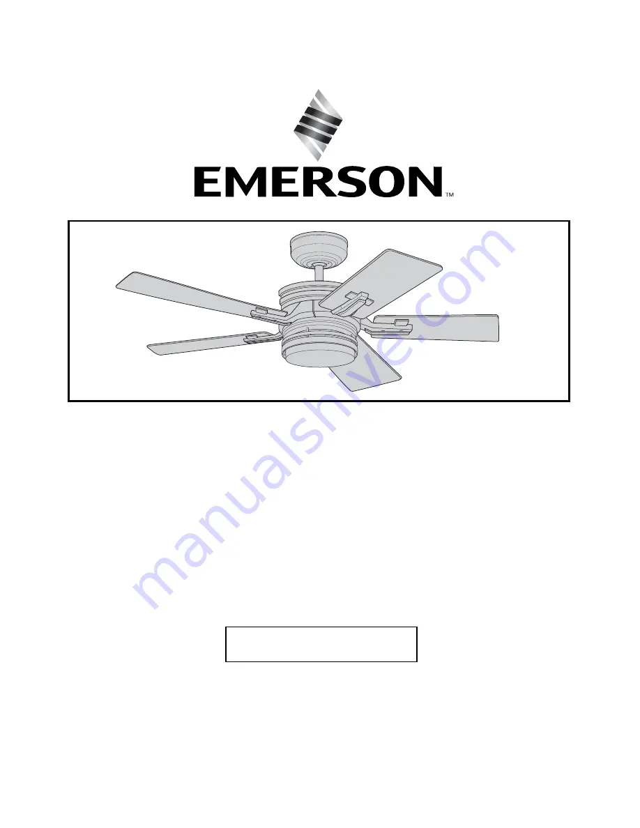
ETL Model No.: CF880

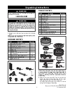
READ AND SAVE THESE INSTRUCTIONS

AMHURST

5

54

4”

”  C

Ce

eiilliin

ng

g  F

Fa

an

n  O

Ow

wn

ne

err''s

s  M

Ma

an

nu

ua

all

Model Numbers

CF880BS00 - 

Brushed Steel

CF880VNB00 - 

Venetian Bronze

CF880VS00 - 

Vintage Steel

Net Weight: 

25.6

Lbs.

Questions, problems, missing parts: Before returning to the store call

Emerson Electric Customer Service 

8 a.m. - 6 p.m., EST, Monday-Friday

1-800-654-3545

www.emersonfans.com

Summary of Contents for AMHURST CF880BS00

Page 1: ...i in ng g F Fa an n O Ow wn ne er r s s M Ma an nu ua al l Model Numbers CF880BS00 Brushed Steel CF880VNB00 Venetian Bronze CF880VS00 Vintage Steel Net Weight 25 6 Lbs Questions problems missing parts Before returning to the store call Emerson Electric Customer Service 8 a m 6 p m EST Monday Friday 1 800 654 3545 www emersonfans com ...

Page 2: ...n blades at least 7 feet from the floor to prevent accidental contact with the fan blades 6 Follow the recommended instructions for the proper method of wiring your ceiling fan If you do not know enough about electrical wiring have your fan installed by a licensed electrician WARNING To reduce the risk of electrical shock this fan must be installed with an isolating wall control switch NOTE This f...

Page 3: ...ing contact your local retailer or catalog outlet for replacement before proceeding 2 Remove the fan assembly from the protective plastic bag Place the fan assembly into the upper foam pad with the top of the motor facing up The upper foam pad serves as a holder for the fan during the first stages of assembly J H I L A G B C E K D F OFF ON PACKAGE CONTENTS 1 3 10 2 7 4 6 5 8 9 HARDWARE CONTENTS Pa...

Page 4: ...talled 4 While pulling up on the downrod tighten the two setscrews in the motor coupler Figure 2 Before assembling your ceiling fan refer to section on proper method of wiring your fan page 9 If you feel you do not have enough wiring knowledge or experience have your fan installed by a licensed electrician WARNING This Manual Is Designed to Make it as Easy as Possible for You to Assemble Install O...

Page 5: ...tach the blade flange to the fan blade using the 10 32 x 1 4 washer head screw Use three screws with lockwashers per blade assembly Figure 4 10 Repeat this procedure for the remaining four blades and flanges NOTE Take care not to scratch fan housing when installing blades 11 Install one blade assembly on the top of the motor housing using two 1 4 20 x 1 2 pan head screws with lockwashers supplied ...

Page 6: ... of the motor connector Figure 7 Engage the black wire connector of the light kit assembly with the black wire connector of the motor connector Make sure the connector latches are closed properly 16 Remove one of the screws from the light kit adapter Retain for future installation Loosen the two remaining screws in the light kit adapter for installation of the light kit assembly 17 Carefully tuck ...

Page 7: ...avings rely heavily on the proper installation and use of the ceiling fan Here are a few tips to ensure quality and product performance Choosing the Appropriate Mounting Location Ceiling fans should be installed or mounted in the middle of the room and at least 7 feet above the floor and 18 inches from the walls If ceiling height allows install the fan 8 9 feet above the floor for optimal airflow ...

Page 8: ...rsonal injury mount fan to outlet box marked Acceptable for Fan Support of 22 7 kg 50 lbs or less and use screws supplied with outlet box Most outlet boxes commonly used for support of light fixtures are not acceptable for fan support and may need to be replaced Consult a qualified electrician if in doubt WARNING The fan must be hung with at least 7 of clearance from floor to blades Figure 9 WARNI...

Page 9: ...ound wire 2 Refer to Figure 12 and 13 and connect the receiver wires to the supply wires and the fan motor wires as follows a Securely connect the green grounding wires from the hanger ball and the hanger bracket to the supply grounding conductor this may be a bare wire or a wire with green insulation b Securely connect the supply white neutral wire to the receiver white AC IN N wire c Securely co...

Page 10: ... the top edge of the glass with the three light kit tips on the light kit assembly and turn the glass bowl clockwise until it is secure Figure 15 NOTE It is advisable to periodically check that the glass is seated fully clockwise in the light kit assembly Over lamping the fan will result in the light bulbs being automatically shut off Use only 60 watt maximum candelabra light bulbs Turn off the el...

Page 11: ...e starting disconnect power to the circuit at the fuse box or circuit breaker panel 7 Remove the faceplate and screws from the existing wall switch Pull switch out from wall outlet box Figure 17 8 Disconnect wire from existing fan wall switch Setting Operating Frequency of Wall Control Your wall control has code switches which must be set in one of 32 possible code combinations The five levers num...

Page 12: ...OL WITH FACE PLATE WALL BOX TO LOAD TO 120VAC SOURCE G R O UND OFF ON HIGH TO LOW BUTTONS ON OFF SWITCH O OFF ON LIGHT BUTTON FAN BUTTON POWER INDICATOR LIGHT OFF ON Figure 19 Figure 20 Operation of Your Reverse Switch IMPORTANT Fan installation must be completed including the installation of the fan blades before testing of the controls 17 Restore electrical power to the outlet box by turning the...

Page 13: ...enance This product is designed to use only those parts supplied with this product and or any accessories designated specifically for use with this product by Emerson Electric Co Substitution of parts or accessories not designated for use with this product by Emerson Electric Co could result in personal injury or property damage WARNING 1 Ceiling Fan Light Controls see store or catalog 2 Downrod E...

Page 14: ...Solid State speed control variable speed controls If Solid State Control is used and motor noise results choose an alternative control method 5 Screws holding blades to flanges are loose 5 Tighten screws securely 3 Fan wobbles 1 Setscrews in motor coupler are not 1 Raise coupler cover and tighten setscrews securely excessively tightened securely 2 Setscrew in the hangerball downrod assembly is 2 T...

Page 15: ...Notes 15 emersonfans com Please contact 1 800 654 3545 for further assistance ETL Model No CF880 ...

Page 16: ...16 ETL Model No CF880 Repair Parts 1 5 2 3 14 21 4 13 15 18 16 11 17 19 20 10 12 12 OFF ON 8 9 6 7 ...

Page 17: ... 761655 93 Consisting of 1 Hanger Bracket 2 Hanger Ball 3 Downrod Parts Bag Containing 764397 1 764397 764397 4 Wire Connector 3 5 Threaded Stud 2 6 Lockwasher 2 7 Knurled Knob 2 8 Pin Clevis 9 Clip Hairpin 10 Screw Pan Head 1 4 20 x 1 2 11 11 Screw Washer Head 10 32 x 1 4 16 12 Screw Pan Head 8 32 x 3 8 1 13 Blade Balance Kit 14 Ceiling Canopy 764332 BS 764332 VNB 764332 VS 15 Coupler Cover 76440...

Page 18: ...18 ETL Model No CF880 Notes ...

Page 19: ...s limited warranty You can return your Emerson Ceiling Fan to your place of purchase or you can call Emerson Customer Service at 1 800 237 6511 to obtain a return authorization and service identification tag In order for us to confirm that your Emerson Ceiling Fan is still under warranty please retain your receipt or other proof of purchase and have that information readily available when returnin...

Page 20: ...er Service 8 a m 6 p m EST Monday Friday 1 800 654 3545 www emersonfans com Retain this manual for future use Air Comfort Products DIVISION OF EMERSON ELECTRIC CO 8100 W Florissant St Louis MO 63136 Part No F40BP74720000 Form No BP7472 Revision 130701 Printed in China 07 13 ETL Model No CF880 ...

Reviews: