

Oil Separators / A-W, A-F, A-WZ
Oil Separators / A-W, A-F, A-WZ
Instruction Sheet
PA-00376
October 2014
General Information
The function of an oil separator is to separate oil from the
hot gas in the discharge line and return it to the compressor
crankcase or to the oil reservoir in systems with multiple
compressors.
Application
• Multiple compressor racks for supermarkets and air
conditioning
• Systems with long refrigerant lines
• Systems with inherent oil return problems
• Ultra-low temperature systems
• For use with HCFCs, HFCs and their lubricants
Features
• Hermetic welded or accessible bolted flange construction.
• Solid copper connections
• Corrosion resistant paint
Specifications
• A-W, A-F Maximum working pressure: 450 psig
• A-WZ Maximum working pressure: 600 psig
Safety Instructions
• Read installation instructions thoroughly. Failure to
comply can result in device failure, system damage or
personal injury.
• It is intended to be installed by persons having the
appropriate knowledge and skill. Before attempting to
install, make sure pressure in system is brought to and
remains at atmospheric pressure.
• Do not release any refrigerant into the atmosphere.
• Do not use any other fluid media without prior approval
of Emerson Climate Technologies. Use of fluid not listed
could result in change of hazard category of the product
and consequently change of conformity assessment
requirement for product in accordance with European
pressure equipment directive 97123/EC or countries
where applied.
• In a severely contaminated system, avoid breathing acid
vapor and avoid contact with skin from contaminated
refrigerant lubricants. Failure to do so could result in injury.
• The oil separator must be used only for the purpose it is
designed for.
Mounting Location
The oil separator should be installed as close as possible to the
compressor(s) in the main discharge line but after any installed
muffler or vibration absorber.
Please make sure piping is adequately supported to prevent
excessive vibration and stress on the connections.
Caution:
Prevent the migration of liquid refrigerant back
into the oil separator shell during off-cycles by one of the
following recommendations:
- Install the oil separator in a location where it is higher than
the condenser.
- If the oil separator is located slightly lower than the
condenser, install the line from the oil separator to the
condenser at higher level than the condenser and with
a downward slope into the condenser inlet connection.
- In systems where the condenser is located higher than the
oil separator, it is recommended to use a check valve at the
outlet of oil separator.
Installation
Before proceeding with the installation, the oil separator
must be charged with a certain amount of oil in order to actuate
the float mechanism immediately after start-up. Use the same
type of oil as in the compressor.
- 0.5 liter (17 oz.) initial oil charge for A-W, A-F, A-WZ 4 in.
diameter models
- 0.6 liter (20 oz.) initial oil charge for A-W, A-F 6 in.
diameter models.
- 0.74 liter (25 oz.) initial oil charge for A-WZ 6 in.
diameter models.
• The oil must be charged through the outlet connection
• The oil separator shell must be mounted securely in a
vertical
position.
Warning
Protect the oil separator against vibration and gas pulsation
generated by the compressor. Install a vibration absorber and
muffler between the compressor and the oil separator.
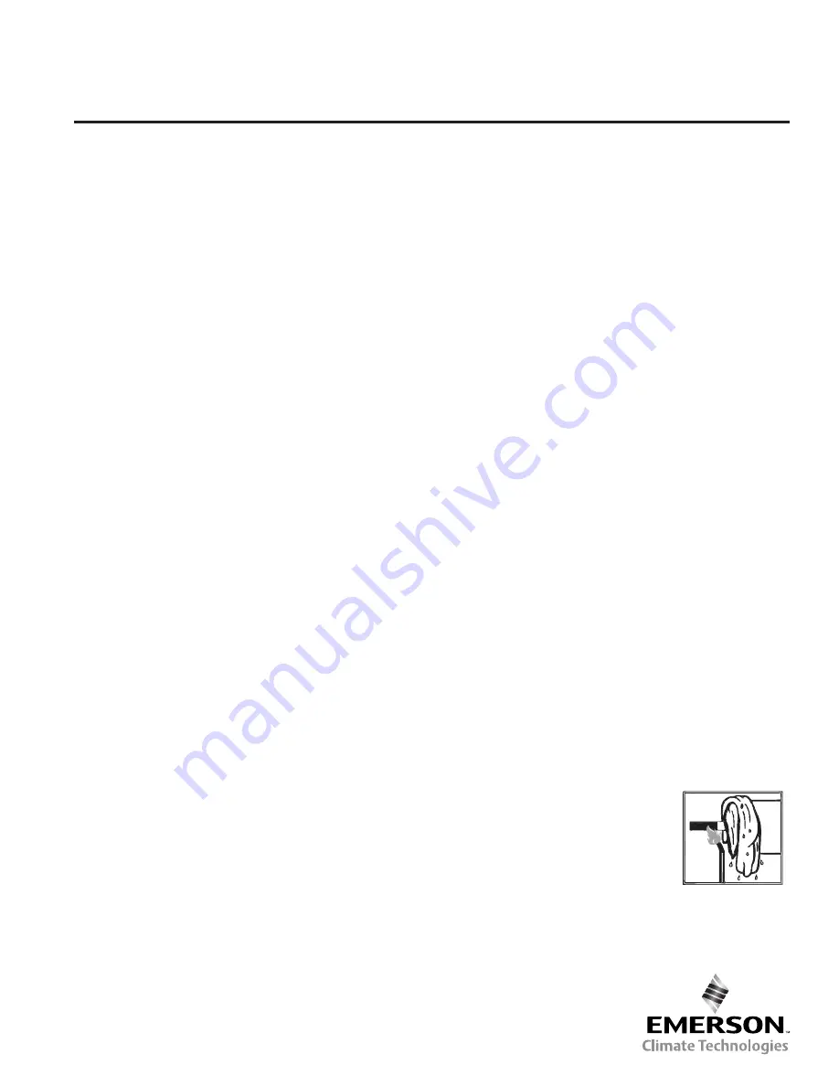
• When brazing, direct the flame away from shell. Use wet
rags or other suitable heat protection to prevent damage to
the paint surfaces adjacent to the fittings.
• Use the correct temperature for brazing copper to copper
as the fittings of the shell are solid copper. Do not exceed
675°C flame temperature.
• Purging dry nitrogen through the lines during brazing will
prevent oxide scale (solid particles) from forming
on the inside of the brazed joints. These particles can jam
the float mechanism and clog the needle valve.
Caution:
The oil separator F Type
with a flange cap incorporates a gasket.
Do not exceed 150°C around the flange.
If so, the gasket can be damaged and it
must be replaced. Keep the flange cap
cool during brazing.
• The oil return line (minimum 3/8" or 10 mm) should be
connected to the compressor crankcase or to the oil
reservoir in the systems with multiple compressors.


