

Document Part # 026-4247 Rev 4
Page 1 of 2
©2017 Emerson Climate Technologies Retail Solutions, Inc. This document may be photocopied for personal use.
Visit our website at http://www.emersonclimate.com/ for the latest technical documentation and updates.
For a copy of the full Wireless User Manual (
P/N 026-1734
), go to
http://www.emersonclimate.com/qrcode004
to download it or
contact Emerson Retail Solutions Customer Service at
770-425-2724.
Emerson’s Wireless Module System allows for quickly and easily
monitoring a variety of Refrigeration and HVAC applications by
connecting temperature probes, product simulators, humidity
probes or switches to the Wireless Module that transmits these
signals to the Wireless Gateway. The Gateway translates the
signal into usable information to send to the building controller,
E2 (version 4.08 or higher) or Site Supervisor, where the data
can be logged into reports or used by algorithms to make
control decisions. The Wireless Gateway can receive signals
from up to 99 Modules. The Wireless Module is flexible and
configurable with up to three (3) analog or digital inputs that
can be used for a variety of applications in Refrigeration and
HVAC, eliminating installation materials and costly
labor-intensive wiring.
Installing the Wireless Gateway
Installing the Emerson Wireless Gateway for E2 involves
mounting and powering the device, and connecting to E2’s
RS485 network.
Figure 1 - Wireless Gateway Enclosure Dimensions
The Emerson Wireless Gateway requires 24VAC power from a
Class 2 Transformer.
Because the Gateway is usually mounted away from the
transformer, 18 AWG wire should be used. The AC voltage at
the Gateway needs to be at least 19 Volts.
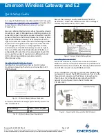
Figure 2 - Emerson Wireless Gateway Board
Installing Network Cable
Each E2 that will receive a value from an Emerson Wireless
Module must have an Emerson Wireless Gateway installed on its
RS485 Network. For E2 controllers, the Gateway will be installed
on an RS485 network running MODBUS protocol.
Using a shielded three-conductor network cable (Belden #8641
or equivalent), connect the RS485 Network wire from E2 to the
three-terminal connector on the Wireless Gateway board as
shown below. For further information about how RS485
networks are configured, refer to the E2 User Manual
(
P/N 026-1614
).
Figure 3 - Connecting the Gateway to the RS485 Network
Input Voltage
24VAC, Class 2, 50/60Hz
Power
10VA
Table 1 - Wireless Gateway Power Requirements
Quick Setup Guide
Emerson Wireless Gateway and E2


