background image

381333–133 A

50 Hanover Road, Florham Park, New Jersey 07932–1591 USA

1 800 937–2726 (ASCO), for service call 1 800 800–2726 (ASCO) www.asco.com

ASCO POWER TECHNOLOGIES CANADA PO Box 1238, 17 Airport Road, Brantford, Ontario, Canada N3T 5T3

telephone 519 758–8450, fax 519 758–0876, for service call 1 888 234–2726 (ASCO) www.asco.ca

Operator’s

Manual

7000 Series ATB

Automatic Transfer &

Bypass–Isolation Switches

F–design, 3000 and 4000 amp. sizes

TABLE OF CONTENTS

section-page

INSTALLATION

1-1

. . . . . . . . . . . . . . . . . . . . . . . .

Mounting

1-1

. . . . . . . . . . . . . . . . . . . . . . . . . . . . .

Power Connections

1-2

. . . . . . . . . . . . . . . . . . . .

Engine Starting & Auxiliary Circuits

1-2

. . . . . .

Functional Test

1-5, 1-6, 1–7

. . . . . . . . . . . . . . . .

TESTING & SERVICE

2-1

. . . . . . . . . . . . . . . . . .

Transfer Test

2-1

. . . . . . . . . . . . . . . . . . . . . . . . . .

Preventive Maintenance

2-1

. . . . . . . . . . . . . . . .

Disconnecting the Controller

2-1

. . . . . . . . . . . .

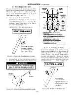
Manual Load Transfer

2-2

. . . . . . . . . . . . . . . . . .

Trouble-Shooting

2-2

. . . . . . . . . . . . . . . . . . . . . .

BYPASSING & ISOLATING

3-1

. . . . . . . . . . . . . .

Bypassing the ATS

3-1

. . . . . . . . . . . . . . . . . . . .

Isolating the ATS

3-1

. . . . . . . . . . . . . . . . . . . . . .

Return to Service

3-3

. . . . . . . . . . . . . . . . . . . . . .

INDEX

back cover

. . . . . . . . . . . . . . . . . . . . . . . . .

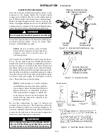
An experienced licensed electrician must install ATB

Refer to the outline and wiring drawings provided

with your 7000 Series ATB for all installation and

connection details and accessories.
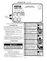
Refer to

Group 5 Controller User’s Guide

381333–126

for ATS status display messages, time delays, pickup

& dropout settings, and adjustments.

Rating Label

Each 7000 Series ATB contains a rating label to define the

loads and fault circuit withstand/closing ratings. Refer to the

label on the Transfer Switch for specific values.

Do not exceed the values on the rating label.

Exceeding the rating can cause personal injury

or serious equipment damage.

!

Nameplate

The Transfer Switch nameplate includes data for each

specific 7000 Series ATB. Use the switch only within the

limits shown on this nameplate. A typical Catalog Number

is shown below with its elements explained:

Catalog Number Identification

Typical 7000 Series ATB catalog no. for overlapping neutral, 3 pole, 4000 amp, 480 V, in Type 1 enclosure:

7ATB

C

3

4000

N

5

C

Phase Poles

Neutral

A

– solid

Amperes

Voltage

Controller

Enclosure

5X

– if accesso-

ries ordered

5

– standard

G

– type 4

C

– type 1

F

– type 3R

L

– type 12

3

– three Ø

2

– single Ø

B

120

D

220

A

115

C

208

E

230

K

415

M

460

J

400

L

440

N

480

G

277

F

240

H

380

Q

575

P

550

R

600

4000

3000

blank --- none

blank – open type

C

– overlapping

Summary of Contents for 7ATBC34000N5C

Page 1: ... installation and connection details and accessories Refer to Group 5 Controller User s Guide 381333 126 for ATS status display messages time delays pickup dropout settings and adjustments Rating Label Each 7000 Series ATB contains a rating label to define the loads and fault circuit withstand closing ratings Refer to the label on the Transfer Switch for specific values Do not exceed the values on...

Page 2: ...equired door opening space If bottom cable entry is used the foundation must be pre pared so that conduit stubs are located correctly Refer to appropriate enclosureoutline drawingfor specifiedcable entrance area and location Provide cable bending space andclearancetolivemetal parts When aconcrete flooris poured use interlocking conduit spacercaps ora woodor metal template to maintain proper condui...

Page 3: ...ection is used use SAE grade 5 hardware to connect bus to appropriate terminal plates on bypass switching device Wipe off bus surfaces before they are joined If bus is dirty gently clean surfaces with a non flammablesolvent Avoidtouching cleanedsurfaces Do not breathe cleaning solvent vapors Use SAE grade 5 hardware and tighten the bolted joints to the torque specified in Table 2 1 The reliability...

Page 4: ... roll it into the cabinet isolation contacts facing inward Align the rollers between the floor guides and push the carriage in until its crank pins engage the latch plates on both sides Then follow the procedure below NOTE Solenoid lock SL1 on the Isolation shaft inhibits operation of the drawout Isola tion contacts unless the Transfer Switch and Bypass Switch are in compatible positions This sole...

Page 5: ...nterference tag in place Figure 1 2 continue slowly turning the Isolation Handle clockwise until it stops approximately 6 or 7 turns Now remove the interference tag from the solenoid latch Observe The Transfer Switch should be pulled inward the isolation contact fingers should make with the male stabs as shown in Figure 1 6 Also check that the Bypass Switch switched neutral contacts have opened Fi...

Page 6: ...g a meter to measure voltages Do not touch power termi nals shock burns or death could result Perform steps 1 6 at the right Observe the status lights See Figures 1 8 and 1 11 Black square means light is on White square means light is off If necessary adjust voltage regulator on generator per the manufacturer s recommendations The ATB will respond only to rated voltage specified on the nameplate N...

Page 7: ...onnect isolation contacts 2 A detachable manual operator handle is provided on the Transfer Switch for maintenance purposes only Do not manually operate the Transfer Switch unless the Isolation Handle is in the OPEN position and the DISCONNECTED light is on handle rotating weight Figure 1 10 Transfer Switch manual operator handle Figure 1 11 Status Indicator Panel Insert the manual handle into the...

Page 8: ...solation Handle clockwise until it stops about 6 or 7 turns The CONNECTED light should come on TEST light off Remove the Isolation Handle and store it inside the enclosure on the carriage frame on the right side 4 Turn the Bypass Handle clockwise to the AUTO MATIC POS position The Bypass Switch CLOSED ON NORMAL light should go off ThiscompletestheFunctionalTestof theATB Thegenera tor s starting co...

Page 9: ...lation Remove any mois ture with a clean cloth j Check the transfer switch contacts Remove transfer switch barriers and check the condition of the contacts Replace contacts when pitted or worn excessively Reinstall the barriers carefully j Maintain transfer switch lubrication Ifswitchissub jected to severe dust or abnormal operating conditions renew factory lubrication on all movements and link ag...

Page 10: ...ansfer switch does not transfer the load to normal source when normal returns or when the Transfer Control switch is released Wait for Feature 3A time delay to time out Voltmeter should read at least 90 of nominal phase to phase voltage between transfer switch terminals NB NC NC NA NA NB or NL1 NL2 for 2 pole Engine generator set does not stop after load retransfer to the normal source Wait for Fe...

Page 11: ...OLATING NOTE When Acc 66A is specified the handle operation is reversed Follow instruction on the door ISOLATING This procedure explains how to isolate the Automatic Transfer Switch Isolating is required before any service work can be performed on the ATS Observe the ATS POSITION lights on the STATUS INDICATOR panel 1 Bypass the closed Automatic Transfer Switch contacts See BYPASSING 2 Isolate the...

Page 12: ...ng electrical shock burns or death Do not touch isolation contact fingers 1 Open the ATS cabinet doors all the way Remove the bottom louvered enclosure pan if not already removed All arc chutes and interphase barriers must be in place on the Transfer Switch The enclosure tracks and floor in front must be free of debris The Transfer Switch contacts must be closed on the same source that is feeding ...

Page 13: ...This light indicates the source connected to the load 4 Observe which Transfer Switch CLOSED ON light is on NORMAL or EMERGENCY This light indicates the position of the Transfer Switch If it is not in the same position as the Bypass Switch change the Transfer Switch position as follows To change the position of transfer switch Operate to NORMAL Operate to EMERGENCY Turn Transfer Control switch cou...

Page 14: ...2 manual load transfer 2 2 warning 2 2 N nameplate cover Normal Source Accepted light 1 5 O operation electrical 1 7 manual 1 6 warning 1 6 P parts 2 1 phase rotation check 1 2 preventive maintenance 2 1 problem 2 2 R rating label cover replacement parts 2 1 return to service 3 3 S service ASCO Services Inc ASI 2 1 settings see Controller User s Guide T test functional 1 5 1 6 1 7 testing power ca...

Reviews: