background image

Reference Manual

00809-0600-4410, Rev AA

May 2020

Emerson Wireless 1410S Gateway and 781S
Smart Antenna

Summary of Contents for 781S

Page 1: ...Reference Manual 00809 0600 4410 Rev AA May 2020 Emerson Wireless 1410S Gateway and 781S Smart Antenna ...

Page 2: ...2 ...

Page 3: ...rements 35 4 3 Software installation 36 4 4 Security setup utility 36 4 5 AMS Wireless Configurator 37 4 6 Licensing and credits 38 Chapter 5 Operation and maintenance 39 5 1 Overview 39 5 2 Network architecture 39 5 3 Modbus 40 Chapter 6 Troubleshooting 45 6 1 Service support 45 6 2 Initial connection Web browser returns page not found 45 6 3 Initial connection Cannot find Gateway after changing ...

Page 4: ...ications OPC application cannot find a Gateway OPC server 50 6 17 OPC communications Gateway OPC server does not show any Gateways 50 6 18 OPC communications Gateway OPC server does not show any data tags 50 6 19 EtherNet IP Gateway is not publishing the parameters 51 6 20 Return of materials 51 Appendix A Reference data 53 A 1 Ordering information specifications and drawings 53 A 2 Product certif...

Page 5: ...and make electrical connections including electrical wiring grounding and host system connections Section 4 Commissioning describes installation and setup of the optional software included with the Wireless Gateway This software aids in secure host integration and wireless field device configuration Section 5 Operation and Maintenance describes how to connect the Gateway to a host system and integ...

Page 6: ...Introduction Reference Manual May 2020 00809 0600 4410 6 Emerson com ...

Page 7: ... 2 PC requirements Operating system optional software only For security set up Microsoft supported Windows operating systems are acceptable See some examples shown below Microsoft Windows Server 2008 Standard Edition Service Pack 2 Windows 10 Enterprise Service Pack 1 Applications Configuration of the Gateway is done through a secure web interface Recent versions of the following browsers are supp...

Page 8: ...ted the factory IP address is 192 168 1 10 E Ethernet port 2 When this port is activated the factory IP address is 192 168 2 10 F Emerson 1410S power and serial connections CAUTION Equipment damage Connecting through the open terminal block cover the lower cover may stress the connections and damage the Gateway When making physical connections to the Gateway it is important to use the electrical c...

Page 9: ... on the bottom right of the screen 2 Select the Network and Sharing Center 3 Select Local Area Connection 4 Select Properties 5 Select Internet Protocol Version 4 TCP IPv4 Properties Reference Manual Configuration 00809 0600 4410 May 2020 Emerson 1410S 781S 9 ...

Page 10: ...s button 7 In the IP address field enter 192 168 1 12 DeltaV Ready enter 10 5 255 12 8 In the Subnet mask field enter 255 255 255 0 9 Select OK for both the Internet Protocol TCP IP Properties window and the Local Area Connection Properties window 2 3 3 Windows 10 Procedure 1 Select the network icon in the lower right corner 2 Select the Network settings link Configuration Reference Manual May 202...

Page 11: ...3 Select Change adapter options Reference Manual Configuration 00809 0600 4410 May 2020 Emerson 1410S 781S 11 ...

Page 12: ...ion 4 TCP IPv4 Properties Note If the PC laptop is from another network record the current IP address and other settings so the PC laptop can be returned to the original network after the Gateway has been configured 6 Select the Use the following IP address button Configuration Reference Manual May 2020 00809 0600 4410 12 Emerson com ...

Page 13: ...ry Ethernet port will require different network settings Table 2 1 Network Settings Ethernet Gateway PC laptop tablet Subnet 1 192 168 1 10 192 168 1 12 255 255 255 0 2 192 168 2 10 192 168 2 12 255 255 255 0 2 3 4 Disable proxies Use these steps to disable proxies Procedure 1 Open web browser 2 Navigate to Tools Internet Options Connections LAN Settings may be a different process for other browse...

Page 14: ...ateway This will need to be done for both the WirelessHART and ISA100 networks Procedure 1 Access the WirelessHART default web page for the Gateway at https 192 168 1 10 You will have to configure both networks individually a Log on as Username admin b Type in password default Configuration Reference Manual May 2020 00809 0600 4410 14 Emerson com ...

Page 15: ...Backup and Restore Restart Apps Note Resetting applications will temporarily disable communications with field devices 2 3 6 User accounts There are four role based user accounts for the Gateway with varying levels of access The access can be changed on the System Settings Users User Accounts by the admin user The figure below displays this access Reference Manual Configuration 00809 0600 4410 May...

Page 16: ...tem Settings Users User Accounts 2 Click the Edit button of the user password to be changed 3 Set the new password for the role based account and confirm 4 Select Save Changes Note It is suggested the default security settings in System Settings Users User Options be changed to the local IT best practices or the Normal setting after initial login Strong or custom settings are available for more ro...

Page 17: ...Protocol NTP server to adjust the Gateway s time to match the time of the control network a Enter the IP address for the NTP server b Select the packet version i e 1 2 3 or 4 2 Set with PC Time This option will match the Gateway s time to the PC Laptop 3 Manual Entry This option allows the user to enter a specific date MM DD YY and time HH MM SS Note Network Time Protocol NTP is recommended for th...

Page 18: ... It is best practice that a System Backup be performed periodically throughout the installation and configuration process Starting with firmware version 4 7 53 a passphrase is required when taking a backup The passphrase is used to encrypt and decrypt the backup This will need to be done two times for both theWirelessHART and ISA100 networks Procedure 1 Navigate to System Settings Gateway Backup a...

Page 19: ...wer to the Gateway 2 Locate the Reset switch label on the back of the Gateway For the Emerson 1410S2 modular housing the switch is located inside the Gateway housing cover on the DIP switch panel board The reset switch is labeled switch 4 3 Slide the switch to the ON position 4 Reconnect the Gateway turn power on to the Gateway 5 Let the Gateway completely boot up approximately 2 minutes During th...

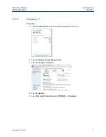
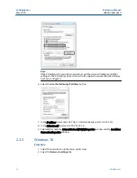
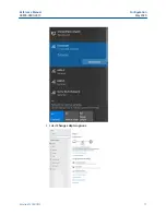
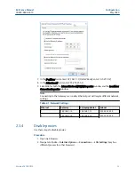
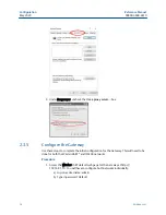
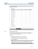
Page 20: ...Configuration Reference Manual May 2020 00809 0600 4410 20 Emerson com ...

Page 21: ...de an electronic enclosure 3 2 Emerson Gateway 1410S2 installation overview This section describes how to properly mount the Emerson 1410S2 Gateway and make electrical connections including wiring grounding and host system connections General considerations The Gateway may be mounted in any general purpose location Be sure the cover is secured tightly to prevent exposure of any electronics to mois...

Page 22: ... positioned near the Gateway The terminals on this connector can accommodate wires from 24 AWG to 12 AWG 18 AWG wire is recommended Tighten screws to 4 4 to 5 3 l bf in 0 5 to 0 6 Nm In ambient temperatures greater than 60 C use wire rated for at least 5 K above the maximum ambient temperature Note Using an uninterruptible power supply UPS is recommended to ensure availability during power failure...

Page 23: ... 2 in pipe Two 5 16 in u bolts supplied with Gateway 2 in mounting pipe in socket head wrench Figure 3 1 Pipe Mount 3 4 2 Bracket mount The following hardware and tools are needed to mount the Gateway to a support bracket Prerequisites Four 15 16 in bolts Mounting support bracket in drill in socket head wrench Mount the Gateway using the following procedure Reference Manual Installing the Gateway ...

Page 24: ...a wireless field network Figure 3 2 shows one of the networks being used Figure 3 2 System Architecture Example Mounting location The Emerson Smart Antenna should be mounted in a location that allows convenient access to the host system network wireless I O as well as the wireless field device network Find a location where the Smart Antenna has optimal wireless performance Ideally this will be 15 ...

Page 25: ...ic horizontal positioning for optimal network connectivity It should be mounted vertically upright in the center of the network for the most direct device connections to the Gateway 3 6 Connecting the Emerson 1410S to the 781S Smart Antennas There are two main connection configurations for the Emerson 1410S and 781S Smart Antennas with and without intrinsically safe barriers The hazardous location...

Page 26: ...cordance with national and local electrical codes The most effective grounding method is a direct connection to earth ground with minimal impedance Ground the Gateway by connecting the external grounding lug to earth ground The connection should be 1Ω or less The external ground plug is located on the left side of the Gateway enclosure and is identified by the following symbol 3 6 2 Ethernet The G...

Page 27: ... located up to 1312 ft 400m from the Emerson 1410S Figure 3 4 Emerson 1410S Gateway and Single 781S Smart Antenna A Emerson Wireless 1410S Gateway B Attach shield pair cable Belden 3084A or equivalent C Tape back shield wire and foils D Emerson Wireless 781S Smart Antenna Reference Manual Installing the Gateway 00809 0600 4410 May 2020 Emerson 1410S 781S 27 ...

Page 28: ...bus RTU on an RS 485 data bus Use 18 AWG single twisted shielded pair wiring to connect the Gateway to the RS 485 data bus The total bus length should not exceed 4000 ft 1220 m Connect the Tx negative receive wire to terminal A and the Rx positive transmit wire to terminal B The wiring shield should be trimmed close and insulated from touching the Gateway enclosure or other terminations If the exi...

Page 29: ... data bus The switches are found inside the electronics housing located in the square opening of the shroud on the upper left side Figure 3 7 The switches number left to right going down from 5 to 1 The downward position on the switch is ON Five DIP switches are provided to enable various terminating resistors to the RS 485 data bus Terminating resistors are on the Emerson 781S connection 120 ohm ...

Page 30: ...and Switch 3 is for the Rx B line These 1 5 kΩ resistors are used to prevent noise from being interpreted as valid communications during periods when no actual communications are occurring Only one set of pull up and pull down resistors should be active on the RS 485 data bus at time Switch 2 is connected to a 120 Ω terminating resistor for Modbus connection This resistor is used to dampen signal ...

Page 31: ...s WLAN Access Points An excellent application is a Gateway connected to a Wi Fi back haul unit such as a Cisco unit For example a Cisco IW6300 unit could power the Gateway over a PoE connection Selecting devices to work with a PoE Gateway When connecting the Gateway to a PSE device it must be labeled as compliant with IEEE 802 3af or IEEE 802 3at Many companies use labels on their packaging such a...

Page 32: ...configuration needed is to flip DIP switch 5 Turning the switch ON means to disable PoE What is the maximum Voltage PoE PSE can source Maximum voltage is normally 48 VDC up to 25 Watts Can you do redundant power with PoE Yes as PoE becomes more popular many network appliance switch providers are supplying innovative switches and other hardware to create redundantly powered networks Typically many ...

Page 33: ...red with the same Network ID and Join Key information Once the field devices are powered they will appear on the wireless network and communications can be verified under the Explore tab using the web interface The time needed for the network to form will depend on the number of devices Reference Manual Installing the Gateway 00809 0600 4410 May 2020 Emerson 1410S 781S 33 ...

Page 34: ...Installing the Gateway Reference Manual May 2020 00809 0600 4410 34 Emerson com ...

Page 35: ...dem Disk 2 Additional system components may be installed depending on the current configuration of the system 4 2 System requirements Table 4 2 PC Hardware Minimum requirements Recommended requirements Intel Core 2 Duo 2 0 GHz Intel Core 2 Quad 2 0 GHz or greater 1 GB Memory 3 GB Memory or Greater 1 5 GB free hard disk space 2 GB or more of free hard disk space Note Additional hard disk space is r...

Page 36: ...tall the software 4 Exit close all Windows programs including any running in the background such as virus scan software 5 Insert disk 2 into the CD DVD drive of the PC 6 Select Install from the menu when the AMS Wireless Configurator setup begins 7 Follow the prompts 8 Allow AMS Wireless Configurator to reboot PC 9 Do not remove the disk from the CD DVD drive 10 Installation will resume automatica...

Page 37: ...communications requires the use of the Security Setup Utility regardless of whether encryption is required 4 5 AMS Wireless Configurator AMS Wireless Configurator helps deploy and configure wireless field devices It provides an HART integrated operating environment that leverages the full capabilities of WirelessHART including embedded data trending charting and graphical display capabilities prov...

Page 38: ... security permissions See the release notes for information specific to the current release of AMS Wireless Configurator To display the release notes navigate to Start Programs AMS Wireless Configurator Help 4 6 Licensing and credits The latest licensing agreements are included on each disk of the software pack This product includes software developed by the OpenSSL Project for use in the OpenSSL ...

Page 39: ...ollowing network architecture diagrams will help when integrating data from the Gateway into the host system Ethernet An Ethernet connection supports Modbus TCP OPC AMS Wireless Configurator EtherNet IP and HART TCP protocols Using this connection type the Gateway is wired directly to a control network see Figure 5 1 using a network switch router or hub Often there are two networks for redundancy ...

Page 40: ... Gateway 5 3 Modbus The Gateway supports both Modbus RTU over the RS 485 serial port and Modbus TCP over Ethernet It functions as a sub device on the Modbus network and must be polled by a Modbus master or client host system Communication settings It is import that the Modbus communication settings in the Gateway match the settings in the Modbus master or client Please refer to host system documen...

Page 41: ...CP IP port settings see the Internal Firewall section for more details Baud Rate The data rate or speed of serial communications This setting is only required for Modbus RTU Parity This setting determines parity none even or odd used for error checking purposes This setting is only required for Modbus RTU Stop Bits This setting determines the number 1 or 2 of stop bits used when ending a message T...

Page 42: ...or This setting causes the Gateway to report a predetermined value when a communications or critical diagnostic error is received from the wireless field device The value is user configurable depending on which floating point representation is chosen See Value reported for error below Value reported for error floating point This setting determines what value is reported if the wireless field devic...

Page 43: ...for each separate data value on the Modbus Mapping page Global scale offset This value is added to the data values for the purpose of scaling integers If global scaling is not selected an offset value will be available for each separate data value on the Modbus Mapping page Reference Manual Operation and maintenance 00809 0600 4410 May 2020 Emerson 1410S 781S 43 ...

Page 44: ...Operation and maintenance Reference Manual May 2020 00809 0600 4410 44 Emerson com ...

Page 45: ...se Incorrect IP address Recommended actions 1 Connect the Gateway and PC laptop 2 Verify the Gateway is properly powered 24 VDC nominal and 250 mA 3 Verify the IP address for the Gateway default primary port is 192 168 1 10 default secondary port is 192 168 2 10 or for DeltaV Ready Gateway s default primary port is 10 5 255 254 default secondary port is 10 9 255 254 4 Verify the IP address of the ...

Page 46: ...erify the Gateway IP address default primary port is 192 168 1 10 default secondary port is 192 168 2 10 3 Verify the IP address of the PC laptop is in the same subnet range as the Gateway i e If Gateway IP address is 155 177 0 xxx then PC laptop IP address should be 155 177 0 yyy 4 Verify this option was ordered with the Gateway 6 5 Initial connection Cannot log into the Gateway Possible cause In...

Page 47: ...ss Configurator server icon in the Windows system tray lower right corner b Select Stop server 6 7 AMS Wireless Configurator Wireless devices do not appear under the Gateway Possible cause Devices not connected Recommended actions 1 Log on to the Gateway and navigate to EXPLORER 2 Right click on wireless network and select Rebuild hierarchy 6 8 AMS Wireless Configurator Wireless device appears wit...

Page 48: ... device has power 2 Verify the device is within effect communications range 3 Verify the proper network ID has been entered into the device 6 11 Wireless field devices Wireless device appears in the join failure list Recommended actions Re enter the network ID and join key into the device 6 12 Wireless field devices Wireless device appears with service denied Possible cause Update rate setting Rec...

Page 49: ...y and navigate to SETUP MODBUS MAPPING 6 14 Modbus communications Cannot communicate using Modbus TCP Possible cause Incorrect settings Recommended actions 1 Verify secure unsecure Modbus protocol settings in the Gateway a Log on to the Gateway b Navigate to SETUP SECURITY PROTOCOLS 2 Verify the Modbus TCP communications settings in the Gateway a Log on to the Gateway b Navigate to SETUP MODBUS CO...

Page 50: ... Navigate to SETUP MODBUS MAPPING 6 16 OPC communications OPC application cannot find a Gateway OPC server Possible cause Incorrect Security Setup Utility installation Recommended actions 1 Verify the Security Setup Utility has been installed on the same PC as the OPC application 2 Configure an OPC proxy for the Gateway see Security setup utility 6 17 OPC communications Gateway OPC server does not...

Page 51: ...ration Recommended actions 1 Verify connection is established with EtherNet IP a Navigate to SETUP SECURITY PROTOCOLS 2 To connect to an Allen Bradley system reference the Integration Manual 6 20 Return of materials To expedite the return process outside of North America contact your Emerson representative Within the United States call the Emerson Response Center toll free number 1 800 654 7768 Th...

Page 52: ...d understand the hazard If the product being returned was exposed to a hazardous substance as defined by OSHA a copy of the required Material Safety Data Sheet MSDS for each hazardous substance identified must be included with the returned goods Troubleshooting Reference Manual May 2020 00809 0600 4410 52 Emerson com ...

Page 53: ... and select the appropriate document 4 For ordering information specifications and dimensional drawings click Data Sheets Bulletins and select the appropriate Product Data Sheet A 2 Product certifications To view current Emerson1410S and 781S product certifications follow these steps Procedure 1 Navigate to the product page for Emerson 1410S and 781S 2 Scroll as needed to the green menu bar and cl...

Page 54: ...lf organizing networks Easy integration into control systems and data applications through serial and Ethernet connections Greater than 99 percent data reliability with industry proven security Ability to leverage sensor data from critical assets to eliminate blind spots and improve productivity and safety of operations Integration to the new Cisco Catalyst IW6300 Heavy Duty Access Point providing...

Page 55: ...eamless integration via LAN or serial communications to other existing host systems Gateways interface with existing host systems via Local Area Network LAN or serial communications using industry standard protocols including OPC DA Modbus TCP IP Ethernet IP HART IP and Modbus RTU Layered security keeps your network safe All wireless data is 128 bit AES encrypted so your data is kept safe All wire...

Page 56: ...ibility WirelessHART gives users the ability to form large networks that self form a wireless mesh giving the user an easy path to build and grow networks To support the transition from legacy protocols to WirelessHART a separate 781S Smart Antenna can be used to connect to legacy ISA100 instrumentation Connect to 200 WirelessHART devices at a single point of communication with the upgraded Emerso...

Page 57: ...on on material selection Model code example Model codes contain the details related to each product Exact model codes will vary an example of a typical model code is shown in Figure 1 Figure 1 Model Code Example XXX X XXX X X XX XXX XXX XX 1 2 1 Required model components choices available on most 2 Additional options variety of features and functions that may be added to products The starred offer...

Page 58: ...order the Emerson 781SC ISA100 Smart Antenna Reference Emerson Wireless 781S Ordering Information for details Ethernet communications physical connection Code Description 1 Single Ethernet connection 2 Dual Ethernet connection Serial communication Code Description N None A Modbus RTU via RS485 Ethernet communications data protocols Code Description D1 Modbus TCP IP D2 OPC DA D3 EtherNet IP D4 Modb...

Page 59: ...guay Peru Philippines Uruguay E63 Albania Algeria Armenia Austria Bahamas Belgium Bosnia and Herzegovina Bulgaria Burundi Cameroon Croatia Cyprus Czech Republic Denmark Estonia Finland France Gabon Germany Ghana Gibraltar Greece Hungary Iceland Ireland Italy Jamaica Jordan Kazakhstan Latvia Liechtenstein Lithuania Luxembourg Macedonia Malta Mauritius Monaco Mongolia Montenegro Morocco Netherlands ...

Page 60: ...int power options 1410S PWR Description P1 High DC power 44 57 VDC P2 Low DC power 10 8 36 VDC P3 AC power 100 200 VAC Cisco Wi Fi access point dual band antenna options Further antenna options can be purchased through the spare parts page Code Description D4 Dual band 1 port omnidirectional antenna with 4 dBi of gain D0 No antenna ordered separately through spare parts Cisco Wi Fi access point mo...

Page 61: ...aser of the equipment See the Material selection section for more information on material selection Model code example Model codes contain the details related to each product Exact model codes will vary an example of a typical model code is shown in Figure 1 Figure 2 Model Code Example XXX X XXX X X XX XXX XXX XX 1 2 1 Required model components choices available on most 2 Additional options variet...

Page 62: ...t certifications Code Description I5 USA Intrinsically Safe I6 Canada Intrinsically Safe I1 ATEX Intrinsic Safety I7 IECEx Intrinsic Safety KD USA Canada Intrinsically Safe ATEX Intrinsic Safety KL USA Canada Intrinsically Safe ATEX IECEx Intrinsic Safety NA No approvals Wireless network capacity Code Description NA1 200 device WirelessHART network NA5 25 device WirelessHART network NC1 99 device ...

Page 63: ...9 F 40 to 65 C Operating humidity range 0 to 99 percent relative humidity Antenna options See Wireless antenna options Performance specifications EMC performance Meet all industrial environment requirements of EN61326 Maximum deviation less than one percent span during EMC disturbance Note During surge event device may exceed maximum EMC deviation limit or reset however device will self recover an...

Page 64: ...ions Wireless output IEC 62591 WirelessHART 2 4 GHz DSSS IEC 62743 ISA100 2 4 GHz DSSS Environmental 0 to 99 percent non condensing relative humidity Radio Frequency power output from antenna Internal antenna WP3 option Maximum of 40 mW 16 dBm EIRP Smart Antenna wiring distance Wiring distance between Smart Antenna and Gateway Up to 400 m using single twisted shielded pair 22 24 AWG 30ft of Belden...

Page 65: ...6 67 rated Performance specifications EMC performance Meet all industrial environment requirements of EN61326 and NAMUR NE 21 Maximum deviation less than 1 span during EMC disturbance Vibration effect No effect when tested per the requirements of IEC60770 1 1999 High vibration level field or pipeline 10 to 60 Hz 0 21 mm displacement peak amplitude 60 to 2000Hz 2g Emerson Wireless 1410S April 2020 ...

Page 66: ...r Switzerland 41 0 41 768 6111 41 0 41 768 6300 RFQ RMD RCC Emerson com Asia Pacific Regional Office Emerson Automation Solutions 1 Pandan Crescent Singapore 128461 65 6777 8211 65 6777 0947 Enquiries AP Emerson com Middle East and Africa Regional Office Emerson Automation Solutions Emerson FZE P O Box 17033 Jebel Ali Free Zone South 2 Dubai United Arab Emirates 971 4 8118100 971 4 8865465 RFQ RMT...

Page 67: ...Reference data Reference Manual May 2020 00809 0600 4410 54 Emerson com ...

Page 68: ...Quick Start Guide 00825 0600 4410 Rev AA March 2020 Emerson Wireless 1410S Gateway ...

Page 69: ...afe installation Avoid contact with leads and terminals High voltage that may be present on leads can cause electrical shock Potential electrostatic charging hazard The Gateway enclosure is aluminum Use care in handling and cleaning when in explosive environments to avoid an electrostatic discharge Physical access Unauthorized personnel may potentially cause significant damage to and or misconfigu...

Page 70: ...e powered up in order of proximity from the Gateway beginning with the closest This will result in a simpler and faster network installation 1 2 Gateway redundancy If the wireless Gateway was ordered with redundancy Gateway Redundancy code RD refer to Appendix D in the Emerson Wireless Gateway Reference Manual for additional installation instructions March 2020 Quick Start Guide Quick Start Guide ...

Page 71: ...s Server 2019 Standard Edition Service Pack 2 Windows 10 Enterprise Service Pack 1 2 2 Applications Configuration of the Gateway is done through a secure web interface Recent versions of the following browsers are supported Chrome browser Mozilla Firefox Microsoft Edge 2 3 Hard disk space AMS Wireless Configurator 1 5 GB Gateway Setup CD 250 MB Quick Start Guide March 2020 4 Emerson com ...

Page 72: ...enna terminal 2 power and data connections D Ethernet port 1 When this port is activated the factory IP address is 192 168 1 10 E Ethernet port 2 When this port is activated the factory IP address is 192 168 2 10 F Emerson 1410S power and serial connections G Power output H RS 485 comm I 10 5 to 30 VDC power input J Serial modbus WARNING Conduit cable entries The conduit cable entries in the trans...

Page 73: ...eceptacle on the Gateway using an Ethernet cable 3 2 Windows 7 Procedure 1 Click the Internet Access icon on the bottom right of the screen Figure 3 2 Internet Access 2 Select the Network and Sharing Center 3 Select Local Area Connection Quick Start Guide March 2020 6 Emerson com ...

Page 74: ... 3 4 Internet Protocol Version 4 TCP IPv4 Note If the PC laptop is from another network record the current IP address and other settings so the PC laptop can be returned to the original network after the Gateway has been configured 6 Select the Use the following IP address button March 2020 Quick Start Guide Quick Start Guide 7 ...

Page 75: ...er 192 168 1 12 DeltaV Ready enter 10 5 255 12 8 In the Subnet mask field enter 255 255 255 0 9 Select OK for both the Internet Protocol TCP IP Properties window and the Local Area Connection Properties window Quick Start Guide March 2020 8 Emerson com ...

Page 76: ...ws 10 Figure 3 6 Network Settings Procedure 1 Select the network icon in the lower right corner 2 Select the Network settings link 3 Select Change adapter options March 2020 Quick Start Guide Quick Start Guide 9 ...

Page 77: ...er Options 4 Right click the network interface connection that the Gateway is plugged into and select Properties 5 Select Internet Protocol Version 4 TCP IPv4 then select Properties Quick Start Guide March 2020 10 Emerson com ...

Page 78: ...op is from another network record the current IP address and other settings so the PC laptop can be returned to the original network after the Gateway has been configured 6 Select the Use the following IP address button March 2020 Quick Start Guide Quick Start Guide 11 ...

Page 79: ...rotocol TCP IP Properties window and the Local Area Connection Properties window Note Connecting to the Gateway s secondary Ethernet port will require different network settings Table 3 1 Network Settings Gateway PC laptop tablet Subnet Ethernet 1 192 168 1 10 192 168 1 12 255 255 255 0 Ethernet 2 192 168 2 10 192 168 2 12 255 255 255 0 Quick Start Guide March 2020 12 Emerson com ...

Page 80: ...ystem section click Open proxy settings Example 3 5 Configure the Gateway To complete initial configuration for the Gateway follow the steps below This will have to be done be done for both networks Procedure 1 Access the default web page for the Gateway at https 192 168 1 10 a Log on as Username admin b Type in password default March 2020 Quick Start Guide Quick Start Guide 13 ...

Page 81: ... Address or set for DHCP and enter a Hostname Figure 3 11 Ethernet Communication b Restart application at System Settings Gateway Backup and Restore Restart Apps Note Resetting applications will temporarily disable communications with field devices 3 Disconnect the power and Ethernet cable from the Gateway Quick Start Guide March 2020 14 Emerson com ...

Page 82: ...y to a 20 in pipe Two 5 16 in u bolts supplied with Gateway 2 in mounting pipe 1 2 in socket head wrench Procedure 1 Insert one u bolt around the pipe through the top mounting holes of the Gateway mounting bracket and through the washer plate 2 Use a 1 2 in socket head wrench to fasten the nuts to the u bolt 3 Repeat for the second u bolt and the lower mounting holes Figure 4 1 Emerson 1410S2 Moun...

Page 83: ...ount the Gateway using the following procedure Procedure 1 Drill four 3 8 in 9 525 mm holes spaced 3 06 in 77 mm apart horizontally and 11 15 in 283 mm apart vertically in the support bracket corresponding with the holes on the Gateway mounting bracket 2 Using a 1 2 in socket head wrench attach the Gateway to the support bracket with four 15 16 in bolts Quick Start Guide March 2020 16 Emerson com ...

Page 84: ...ck shield wire and foils 4 3 Emerson 1410S grounding The Gateway enclosure case should always be grounded in accordance with national and local electrical codes The most effective grounding method is a direct connection to earth ground with minimal impedance Ground the Gateway by connecting the external grounding lug to earth ground The connection should be 1Ω or less The external ground plug is l...

Page 85: ...Figure 1 and Figure 2 for hardware drawings This will have to be done for both networks You can route the networks to different locations if necessary 2 For serial connections make sure all terminations are clean and secure to avoid wiring connection problems 4 6 Best practice Twisted shielded pair cable is generally used to wire the serial connection and it is standard practice to ground the shie...

Page 86: ...ollow the prompts 5 Insert Disk 2 into the CD DVD drive of the PC 6 Select Install from the menu when the AMS Wireless Configurator setup begins 7 Follow the prompts 8 Allow AMS Wireless Configurator to reboot PC 9 Do not remove the disk from the CD DVD drive 10 Installation will resume automatically after login 11 Follow the prompts Note If the autorun function is disabled on the PC or installati...

Page 87: ...to be done for both networks Figure 6 1 Gateway Log In Screen The Gateway is now ready to be integrated into the host system Ensure the field devices to be used with each network have the Network ID and Join Key that is on the Gateway found on the Network Setting page Once the field devices are powered they will appear on the wireless network and communications can be verified under the Explore ta...

Page 88: ...Ta 65 C Standards EN IEC 60079 0 2018 EN IEC 60079 7 2015 A1 2018 EN 60079 11 2012 EN 60079 15 2010 EN 60079 31 2014 N1 ATEX Increased Safety with Intrinsically Safe Outputs to Zone 0 For use only with the Cisco Outdoor Access Point Model IW 6300H AC x K9 Certificate SGS20ATEX0036X Markings II 3 1 G Ex ec nA ia Ga IIC T4 Gc 40 C Ta 65 C Standards EN IEC 60079 0 2018 EN IEC 60079 7 2015 A1 2018 EN ...

Page 89: ...dbus RTU Ethernet Port connections of the equipment must be supplied from either safety extra low voltage SELV or protective extra low voltage PELV circuits for example equipment complying with the requirements of either the IEC 60950 series IEC 61010 1 or a technically equivalent standard 3 The equipment is not capable of withstanding the 500V electrical strength test as defined in clause 6 1 of ...

Page 90: ...thernet Port connections of the equipment must be supplied from either safety extra low voltage SELV or protective extra low voltage PELV circuits for example equipment complying with the requirements of either the IEC 60950 series IEC 61010 1 or a technically equivalent standard 3 The equipment is not capable of withstanding the 500V electrical strength test as defined in clause 6 1 of EN 60079 7...

Page 91: ...r use only with the Cisco Outdoor Access Point Model IW 6300H AC x K9 Certificate IECEx BAS 20 0027X Markings Ex ec nA ic IIC T4 Gc 40 C Ta 65 C Standards IEC 60079 0 2017 IEC 60079 7 2015 A1 2017 IEC 60079 11 2011 IEC 60079 15 2017 IEC 60079 31 2013 Special Conditions for Safe Use X 1 The enclosure s polyurethane paint finish may constitute an electrostatic hazard Care should be taken to protect ...

Page 92: ... BAS 20 0027X Markings Ex tc ic IIC Gc IIIC T90 C Dc 40 C Ta 65 C Standards IEC 60079 0 2017 IEC 60079 7 2015 A1 2017 IEC 60079 11 2011 IEC 60079 15 2017 IEC 60079 31 2013 Special Conditions for Safe Use X 1 The enclosure s polyurethane paint finish may constitute an electrostatic hazard Care should be taken to protect it from external conditions conducive to the build up of electrostatic charge o...

Page 93: ...7 5 Declaration of Conformity Quick Start Guide March 2020 26 Emerson com ...

Page 94: ...March 2020 Quick Start Guide Quick Start Guide 27 ...

Page 95: ...Quick Start Guide March 2020 28 Emerson com ...

Page 96: ... For information on product specs dimensional drawings ordering information or the complete reference manual see Emerson com Figure 8 1 Hazardous Location Installation March 2020 Quick Start Guide Quick Start Guide 29 ...

Page 97: ...x 1046 CH 6340 Baar Switzerland 41 0 41 768 6111 41 0 41 768 6300 RFQ RMD RCC Emerson com Asia Pacific Regional Office Emerson Automation Solutions 1 Pandan Crescent Singapore 128461 65 6777 8211 65 6777 0947 Enquiries AP Emerson com Middle East and Africa Regional Office Emerson Automation Solutions Emerson FZE P O Box 17033 Jebel Ali Free Zone South 2 Dubai United Arab Emirates 971 4 8118100 971...

Page 98: ...Quick Start Guide 00825 0700 4410 Rev AA March 2020 Emerson Wireless 781S Smart Antenna ...

Page 99: ...l national and international standards codes and practices Please review the Product Certifications section for any restrictions associated with a safe installation Electrical shock could cause death or serious injury Avoid contact with the leads and terminals High voltage that may be present on leads can cause electrical shock This device complies with Part 15 of the FCC Rules Operation is subjec...

Page 100: ...Verify operation 11 Product certifications 12 Reference data 21 March 2020 Quick Start Guide Quick Start Guide 3 ...

Page 101: ...mity from the antenna beginning with the closest This will result in a simpler and faster network installation 1 2 Antenna location The antenna should be mounted in a location that allows convenient access to the host system network wireless I O as well as the wireless field device network Figure 1 1 Antenna Mounting Location A Control room B RS 485 cable C Emerson Wireless 781S Smart Antenna D Ma...

Page 102: ...ft 1 m from large structures buildings or conductive surfaces to allow for clear communication to other devices If installing multiple antennas it is important that the antennas have three feet of horizontal separation from one another Figure 1 2 Antenna Position Quick Start Guide March 2020 6 Emerson com ...

Page 103: ...ust be used in conjunction with a network manager or network Gateway The Smart Antenna then functions as a translator between the wired network and a wireless field network Figure 2 1 Example System Architecture March 2020 Quick Start Guide Quick Start Guide 7 ...

Page 104: ...ired and only needs to be connected and powered on the Gateway end The housing is permanently sealed on the Emerson 781S In the Gateway Prerequisites If operating with more than one antenna it is important the antenna is always connected to the antenna terminal connection 1 port Procedure 1 Connect the positive power lead to the power terminal and the negative power lead to the terminal 2 Connect ...

Page 105: ...e 3 2 Wiring Guide A Power B Data Red positive Blk negative Wht RS 485 comm A Blu RS 485 comm B Figure 3 3 Emerson Wireless 781S A Power output B RS 485 comm March 2020 Quick Start Guide Quick Start Guide 9 ...

Page 106: ... used to wire the serial connection to the Gateway The Smart Antenna should be installed in a central location of the wireless field network so that it has the most direct connections to wireless devices as possible Quick Start Guide March 2020 10 Emerson com ...

Page 107: ...rd LED s in the Emerson 1410S correlate to the first and second terminal connections These lights should be green when the antenna is connected properly 5 3 Normal operation The operation of the WirelessHART Smart Antenna can be assessed within the Gateway user interface The connection can be seen by allowing the link to be seen as a field device The operability can be verified by attempting to co...

Page 108: ...ubject to the following two conditions 1 this device may not cause interference and 2 this device must accept any interference including interference that may cause undesired operation of the device Changes or modification to the equipment not expressly approved by Emerson could void the user s authority to operate the equipment Cet appareil est conforme à la Partie 15 de la réglementation FCC Son...

Page 109: ... C Ta 70 C Standards EN IEC 60079 0 2018 EN 60079 11 2012 Special Conditions for Safe Use X 1 The plastic enclosure may constitute a potential electrostatic ignition risk and must not be rubbed or cleaned with a dry cloth 2 The measured capacitance between the equipment enclosure and metallic conduit adapter is 21pF This must be considered only when the Model 781S is integrated into a system where...

Page 110: ...IC T4 Gc 40 C Ta 70 C Standards IEC 60079 0 2017 IEC 60079 11 2011 Special Conditions for Safe Use X 1 The plastic enclosure may constitute a potential electrostatic ignition risk and must not be rubbed or cleaned with a dry cloth 2 The measured capacitance between the equipment enclosure and metallic conduit adapter is 21pF This must be considered only when the Model 781S is integrated into a sys...

Page 111: ...6 6 Declaration of Conformity Emerson Wireless 781SA Smart Antenna March 2020 Quick Start Guide Quick Start Guide 15 ...

Page 112: ...Quick Start Guide March 2020 16 Emerson com ...

Page 113: ...March 2020 Quick Start Guide Quick Start Guide 17 ...

Page 114: ...6 7 Declaration of Conformity Emerson Wireless 781SC Smart Antenna Quick Start Guide March 2020 18 Emerson com ...

Page 115: ...March 2020 Quick Start Guide Quick Start Guide 19 ...

Page 116: ...Quick Start Guide March 2020 20 Emerson com ...

Page 117: ... For information on product specs dimensional drawings ordering information or the complete reference manual see Emerson com Figure 7 1 Hazardous Location Installation March 2020 Quick Start Guide Quick Start Guide 21 ...

Page 118: ...Quick Start Guide March 2020 22 Emerson com ...

Page 119: ...March 2020 Quick Start Guide Quick Start Guide 23 ...

Page 120: ...x 1046 CH 6340 Baar Switzerland 41 0 41 768 6111 41 0 41 768 6300 RFQ RMD RCC Emerson com Asia Pacific Regional Office Emerson Automation Solutions 1 Pandan Crescent Singapore 128461 65 6777 8211 65 6777 0947 Enquiries AP Emerson com Middle East and Africa Regional Office Emerson Automation Solutions Emerson FZE P O Box 17033 Jebel Ali Free Zone South 2 Dubai United Arab Emirates 971 4 8118100 971...

Page 121: ...IP address Must have matching output protocols e g Modbus or OPC on each Gateway Host system Ethernet connection for Modbus TCP or OPC DA communications Serial RS 485 connection for Modbus RTU communications B 3 Setup When configuring redundant Gateways it is only necessary to configure one system The other Gateway will be configured automatically when it is paired with the first Gateway Choose on...

Page 122: ...ttings have been configured the two Gateways must be connected and undergo a pairing process To pair both Gateways and form a redundant system Procedure 1 Connect a PC laptop to the primary Ethernet port on Gateway A 2 Log in using the admin user account 3 Navigate to System Settings Gateway Redundancy Status 4 Connect the secondary Ethernet port on Gateway A to the secondary Ethernet port on Gate...

Page 123: ... standby Gateway on the right If significant configuration changes need to be downloaded to the standby Gateway it may temporarily go offline shortly after the pair process is complete This is expected behavior and does not represent instability in the system Figure B 2 Redundant Pair Reference Manual Redundant Gateway systems 00809 0600 4410 May 2020 Emerson 1410S 781S 57 ...

Page 124: ...ounting and connection practices as a standalone Gateway Refer to Mounting the Emerson 1410S2 Gateway for more information In addition to the standard practices the following considerations should be taken when installing redundant Gateways Redundant Gateway systems Reference Manual May 2020 00809 0600 4410 58 Emerson com ...

Page 125: ...nd HART IP protocols When using this architecture connect the secondary Ethernet port on Gateway A directly to the secondary Ethernet port on Gateway B Then connect the primary Ethernet ports for both Gateways to a process control network using separate redundant network switches See Figure B 5 Figure B 5 Ethernet Connection Architecture A Engineering station B Process control network C Gateway A ...

Page 126: ...ial card E RS 485 bus F Secondary Ethernet Note In either a simplex or dual RS 485 architecture the primary Ethernet ports can be connected to an asset management network to provide connectivity to AMS Device Manager or AMS Wireless Configurator Dual RS 485 A Dual RS 485 host connection support Modbus RTU protocol When using this architecture connect the secondary Ethernet port on Gateway A direct...

Page 127: ...pplied after all primary and secondary Ethernet and RS 485 connections have been made Using separate uninterruptable power supplies UPS is recommended to ensure availability of the redundant Gateway system B 4 Diagnostics The redundant system will perform many diagnostic checks to verify the health and connectivity of the system In the event of a failure it can take up to 30 seconds for the Gatewa...

Page 128: ...oolean REDUNDANT_B_MASTER Indication if Gateway B is the active system REDUNDANT_B_PING Indication if Gateway B is able to ping designated host IP address REDUNDANT_B_ETH0 Electrical connection status of the primary Ethernet port for Gateway A 8 bit unsigned int In addition to the redundancy diagnostics an additional check may be configured to test network connectivity to a host system or other ap...

Page 129: ...eing reintroduced i e it was a part of the original redundant system it will automatically rejoin the redundant system If the Gateway is new or has been set to default configuration it will need to be paired to the current active Gateway Navigate to System Settings Gateway Redundancy and follow the recommended actions on that page or follow the procedure above to pair Gateways and form a redundant...

Page 130: ...Redundant Gateway systems Reference Manual May 2020 00809 0600 4410 64 Emerson com ...

Page 131: ...this installation are required purchasing separate intrinsically safe barriers to use with the dual mode Gateway is recommended C 2 IEC 62734 Network The Emerson 1410S Gateway supports communications to the Emerson 781SC Smart Antenna that communicates through the IEC 62734 standard ISA100 protocol This protocol is intended for legacy devices to be supported while a transition to WirelessHART is m...

Page 132: ...y similarly and can be navigated the same way Devices can be selected and expanding to show detailed device information Although the detailed information isn t as extensive as what you would see from a WirelessHART device more information can still be found on this page A key piece of information that can be found here is the devices role Since ISA100 doesn t have native mesh abilities like a Wire...

Page 133: ...Figure C 3 Detailed Device Information Page Reference Manual Power specifications 00809 0600 4410 May 2020 Emerson 1410S 781S 67 ...

Page 134: ...witzerland 41 0 41 768 6111 41 0 41 768 6300 RFQ RMD RCC Emerson com Asia Pacific Regional Office Emerson Automation Solutions 1 Pandan Crescent Singapore 128461 65 6777 8211 65 6777 0947 Enquiries AP Emerson com Middle East and Africa Regional Office Emerson Automation Solutions Emerson FZE P O Box 17033 Jebel Ali Free Zone South 2 Dubai United Arab Emirates 971 4 8118100 971 4 8865465 RFQ RMTMEA...

Reviews: