


www.Fisher.com
Fisher
™
4320 Wireless Position Monitor
This manual applies to
Device Type
1308 (Hex) 4872 (decimal)
Device Revision
4
Firmware Revision
5
DD Revision
1
Contents
. . . . . . . . . . . . . . . . . . . . . . . . . . . . . . . . .
Scope of Manual
. . . . . . . . . . . . . . . . . . . . . . . . . . . . .
Description
. . . . . . . . . . . . . . . . . . . . . . . . . . . . . . . . .
Terminology
. . . . . . . . . . . . . . . . . . . . . . . . . . . . . . . .
Specifications
. . . . . . . . . . . . . . . . . . . . . . . . . . . . . . .
FCC Compliance
. . . . . . . . . . . . . . . . . . . . . . . . .
Educational Services
. . . . . . . . . . . . . . . . . . . . . . . . .
Installation
. . . . . . . . . . . . . . . . . . . . . . . . . . . . . . . . . .
Installing Standard and Extended Life
Power Module
. . . . . . . . . . . . . . . . . . . . . . . . . . .
Installing Unit Supplied with External
Power Option
. . . . . . . . . . . . . . . . . . . . . . . . . . . .
Network Setup
. . . . . . . . . . . . . . . . . . . . . . . . . . . . .
Using the Field Communicator
. . . . . . . . . . . .
Using AMS Wireless Configurator
or AMS Device Manager
. . . . . . . . . . . . . . .
Hazardous Area Classifications and
Special Instructions for “Safe Use” and
Installations in Hazardous Locations
. . . . . . . . .
Valve / Actuator Mounting
. . . . . . . . . . . . . . . . . . .
Sliding‐Stem (Linear) Actuators
(e.g. Fisher 667)
. . . . . . . . . . . . . . . . . . . . . .
Guidelines for Mounting on Quarter‐Turn
(Rotary‐Shaft) Actuators
. . . . . . . . . . . . . . .
Pneumatic Hookup Procedure for
On/Off Control Option
. . . . . . . . . . . . . . . . . . . . . .
. . . . . . . . . . . . . . . . . . . . . . . . . . . . . . . . . . . . . . .
Communication Connections
. . . . . . . . . . . . . . . . . .
Wireless Communications
. . . . . . . . . . . . . . . . . . . . .
Basic Setup and Configuration
. . . . . . . . . . . . . . . . .
Using the Local User Interface
. . . . . . . . . . . . . . . .
Identifying Device Revision
. . . . . . . . . . . . . . .
Language Selection
. . . . . . . . . . . . . . . . . . . . .
Quick Position
. . . . . . . . . . . . . . . . . . . . . . . . . .
Status
. . . . . . . . . . . . . . . . . . . . . . . . . . . . . . . . .
Power
. . . . . . . . . . . . . . . . . . . . . . . . . . . . . . .
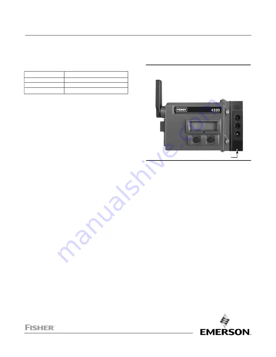
X0899
Figure 1. Fisher 4320 Wireless Position Monitor, with
On/Off Control Option
ON/OFF CONTROL OPTION
Network
. . . . . . . . . . . . . . . . . . . . . . . . . . . . .
Calibrate
. . . . . . . . . . . . . . . . . . . . . . . . . . . .
Using the Field Communicator
. . . . . . . . . . . . . . . .
Overview
. . . . . . . . . . . . . . . . . . . . . . . . . . . . . .
Configure
. . . . . . . . . . . . . . . . . . . . . . . . . . . . . .
Service Tools
. . . . . . . . . . . . . . . . . . . . . . . . . . .
Accessing Features
. . . . . . . . . . . . . . . . . . . . . . . . . . .
. . . . . . . . . . . . . . . . . . . .
. . . . . . . . . . . . . . . . . . . . . . . . .
. . . . . . . . . . . . . . . . . . . . . . . . . . . . . . . . . . . .
Maintenance
. . . . . . . . . . . . . . . . . . . . . . . . . . . . . . . .
Instrument Troubleshooting
. . . . . . . . . . . . . . . . .
Replacing the Instrument
. . . . . . . . . . . . . . . . . . . .
Instrument Removal
. . . . . . . . . . . . . . . . . . . . .
Replacing the Magnetic Feedback Assembly
. . . .
Replacing the Power Module
. . . . . . . . . . . . . . . . .
Removal
. . . . . . . . . . . . . . . . . . . . . . . . . . . . . . .
Installation
. . . . . . . . . . . . . . . . . . . . . . . . . . . . .
Resetting Power Module Variables
. . . . . . . . .
Component Maintenance—On/Off Control Option 60
Spool Valve and Pneumatic Gasket Removal
.
Spool Valve and Pneumatic Gasket Installation 61
Pneumatic Interface and Gasket Removal
. . .
Pneumatic Interface and Gasket Installation
.
. . . . . . . . . . . . . . . . . . . . . .
Instruction Manual
D103621X012
4320
January 2018


