background image

P

OWER

 A

VAILABILITY

3U MP2-220N POD™

U

SER

 M

ANUAL

Power Output

Distribution

208 Volt

16 Amp

Summary of Contents for 3U MP2-220N POD

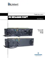
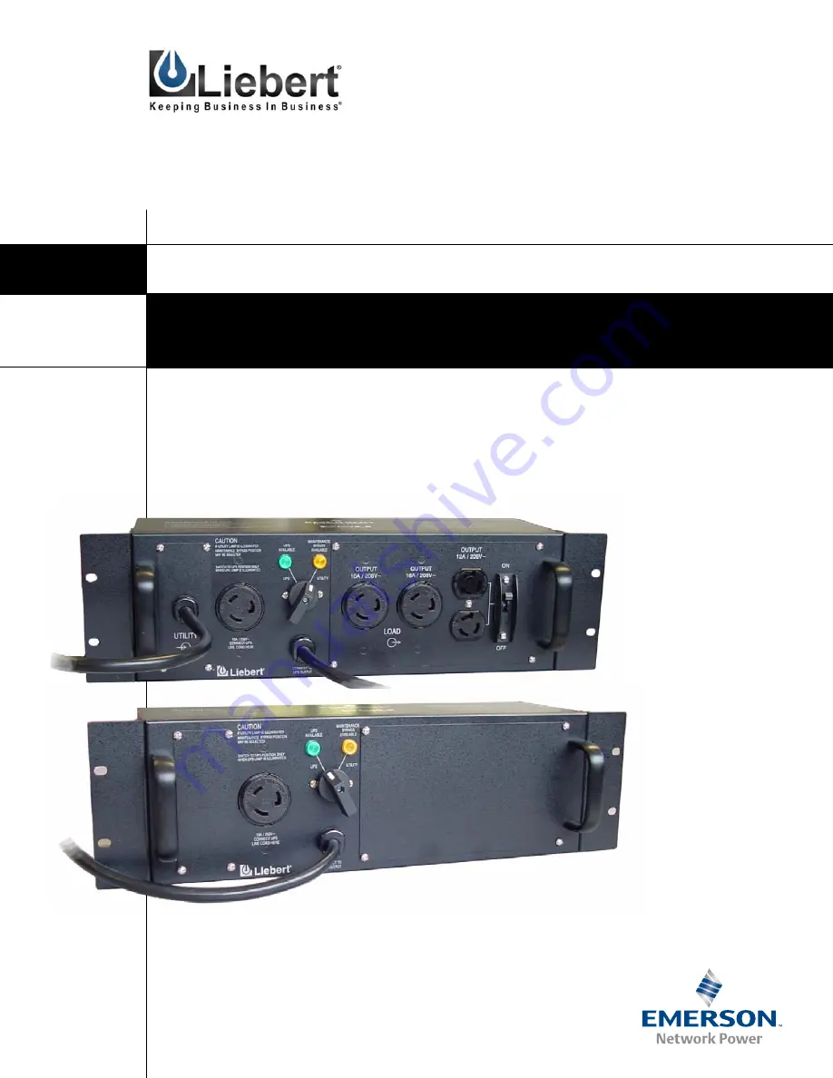
Page 1: ...POWER AVAILABILITY 3U MP2 220N POD USER MANUAL Power Output Distribution 208 Volt 16 Amp ...

Page 2: ......

Page 3: ... 6 4 3 Conversion From Cord Receptacle to Hardwire 7 5 0 INDICATOR LAMPS 8 5 1 UTILITY Indicator Lamp 8 5 2 UPS Indicator Lamp 8 6 0 OPERATION 9 6 1 Transfer to Maintenance Bypass 9 6 2 Transfer to UPS 9 7 0 TROUBLESHOOTING 10 8 0 SPECIFICATIONS 11 8 1 Product Warranty Registration 11 FIGURES Figure 1 UPS mode of operation 3 Figure 2 UTILITY maintenance bypass mode 3 Figure 3 Front panel view show...

Page 4: ...ii ...

Page 5: ...nstall in a clean temperature controlled indoor area free of conductive contaminants Route power supply cords so they are not walked on or pinched in anyway WARNING Do not attempt to service this product yourself Opening or removing the cover may expose you to dangerous voltages even when the AC cord is disconnected from the electrical socket Refer all servicing to qualified service personnel WARN...

Page 6: ...2 GLOSSARY OF SYMBOLS Equipment grounding conductor Bonded to ground Electric phase Indicates AC input Indicates AC output Indicates caution followed by important instructions ...

Page 7: ...und bypassing the UPS system see Figure 2 Util ity power is supplied directly to the load through the 3U POD Figure 2 UTILITY maintenance bypass mode In Utility mode the UPS may be turned off and removed without affecting the load See Figure 3 Figure 3 Front panel view showing plug in connections to and from the UPS CAUTION Battery back up and conditioned power are NOT available during the UTILITY...

Page 8: ...ce it in that direction then attach the brackets to the 3U POD with the two 2 screws provided for each bracket 5 Consult your rack enclosure manufacturer s recommendations for specific rack mounting hardware that will be required 6 Tighten the 3U POD securely to the rails Figure 4 3U POD with rack mounting brackets UP S AV AILA BL E MAINT EN AN CE BY PA SS AV AILA BL E UT ILITY UP S OUTPUT 16A 208...

Page 9: ...trically live The UTILITY lamp amber should be illumi nated 4 Plug the UPS input cord into the receptacle on top of the 3U POD labeled CONNECT UPS LINE CORD HERE WARNING The UPS system is now electrically live 5 Connect the second 3U POD input cord labeled UPS into the matching load receptacle on the rear of the UPS 6 Plug in all loads to the load receptacles The 3U POD now powers your equipment i...

Page 10: ...nduit Entry and Wiring Access Doors The side and rear of the 3U POD provide alternate conduit entry points for both UTILITY and LOAD connections 4 2 Electrical Connections The cable sizes and distribution methods used during installation are subject to local and national electrical codes of practice and are therefore not listed in this manual Table 2 shows the standard current ratings WARNING This...

Page 11: ...hardwire access plates supplied with the unit using the eight screws removed in Step 1 6 The unit is now ready to use Properly grounded earthed equipment provides multiple benefits High quality ground earth connections are required for the equipment ground conductors protective earth and grounding electrode conductor power system earth connection to reduce electrical noise and provide for safe ope...

Page 12: ...ility power outage this lamp will be off and the UPS will supply battery back up power to the con nected loads 5 2 UPS Indicator Lamp This green lamp is illuminated when there is output power available from the UPS see Figure 5 It signals that it is safe to transfer the connected loads from utility power back to UPS output power Figure 5 Indicator lamps on MP2 220N POD Green lamp Output power avai...

Page 13: ...mp is illuminated on the 3U POD 3 Turn the UPS off 4 Disconnect the two cables connecting the UPS to the 3U POD 5 You may now service the UPS 6 2 Transfer to UPS To transfer to UPS from maintenance bypass utility use the following steps 1 Reconnect the UPS to the 3U POD Start the UPS according to the instructions in the UPS user manual 2 Verify that UPS lamp green on the 3U POD is illuminated If s...

Page 14: ...lation UPS Available lamp green not illuminated UPS output power not present Turn on the UPS Refer to the UPS user manual UPS input and or output cord not connected to 3U POD Refer to the 3U POD installation instructions in this manual 2 0 Rack Mount Installation 3 0 Installation and Electrical Connections 4 0 Alternate Hardwire Installation 3U POD will not start some all connected loads Input pow...

Page 15: ...iebert com Click on Product Warranty Registration and fill in the form If you have any questions please contact us at US 800 222 5877 Outside the US 614 841 6755 upstech liebert com Transfer Time to and from maintenance bypass 6 milliseconds Operating Ambient Temperature 32 F to 104 F 0 C to 40 C Storage Ambient Temperature 4 F to 140 F 20 C to 60 C Dimensions with brackets W x D x H in mm 19 0 x ...

Page 16: ...Specifications 12 ...

Page 17: ......

Page 18: ...s all liability for damages resulting from use of this information or for any errors or omissions 2003 Liebert Corporation All rights reserved throughout the world Specifications subject to change without notice Liebert and the Liebert logo are registered trademarks of Liebert Corporation All names referred to are trademarks or registered trademarks of their respective owners SL 23161 7 03 Rev 0 T...

Reviews: