

1592006207 XB570L GB r1.1 23.03.2015 XB570L
1/20
XB570L
BLAST CHILLER - QUICK CHILL AND HOLD FUNCTION
CONTENTS
1.
PLEASE READ BEFORE USING THIS MANUAL ....................................................................................... 1
2.
SAFETY PRECAUTIONS ............................................................................................................................. 1
3.
GENERAL FEATURES ................................................................................................................................. 2
4.
MOUNTING & INSTALLATION ..................................................................................................................... 2
5.
ELECTRICAL CONNECTIONS .................................................................................................................... 2
6.
CONNECTIONS ............................................................................................................................................ 2
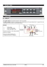
7.
FRONTAL PANEL......................................................................................................................................... 1
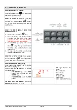
8.
QUICK START .............................................................................................................................................. 1
9.
HOW TO SELECT A CYCLE ........................................................................................................................ 6
10.
PARAMETERS ............................................................................................................................................. 7
11.
HOW A CYCLE IS DONE. .......................................................................................................................... 10
12.
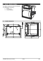
INSTALLATION AND MOUNTING ............................................................................................................. 12
13.
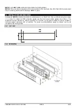
XB07PR - PRINTER (OPTIONAL) .............................................................................................................. 13
14.
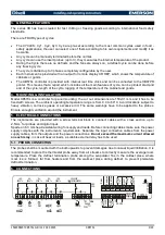
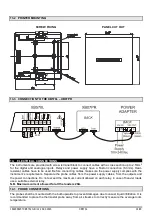
ELECTRICAL CONNECTIONS .................................................................................................................. 14
15.
TTL SERIAL LINE ....................................................................................................................................... 15
16.
USE OF THE PROGRAMMING “HOT KEY “ ............................................................................................. 15
17.
ALARM SIGNALS ....................................................................................................................................... 15
18.
TECHNICAL DATA ..................................................................................................................................... 16
19.
STANDARD VALUE OF THE CYCLES. ..................................................................................................... 16
20.
STANDARD VALUES OF THE PARAMETERS. ........................................................................................ 17
1. PLEASE READ BEFORE USING THIS MANUAL
•
This manual is part of the product and should be kept near the instrument for easy and quick
reference.
•
The instrument shall not be used for purposes different from those described hereunder. It cannot be
used as a safety device.
•
Check the application limits before proceeding.
•
Dixell Srl reserves the right to change the composition of its products, even without notice, ensuring
the same and unchanged functionality.
2. SAFETY PRECAUTIONS
•
Check the supply voltage is correct before connecting the instrument.
•
Do not expose to water or moisture: use the controller only within the operating limits avoiding sudden
temperature changes with high atmospheric humidity to prevent formation of condensation
•
Warning: disconnect all electrical connections before any kind of maintenance.
•
Fit the probe where it is not accessible by the End User. The instrument must not be opened.
•
In case of failure or faulty operation send the instrument back to the distributor or to “Dixell S.r.l.” (see
address) with a detailed description of the fault.
•
Consider the maximum current which can be applied to each relay (see Technical Data).
•
Ensure that the wires for probes, loads and the power supply are separated and far enough from each
other, without crossing or intertwining.
•
In case of applications in industrial environments, the use of mains filters (our mod. FT1) in parallel
with inductive loads could be useful.


