background image


(07/04) 


N

N

e

e

t

t

w

w

o

o

r

r

k

k


P

P

o

o

w

w

e

e

r

r


S

S

w

w

i

i

t

t

c

c

h

h


S

S

i

i

n

n

g

g

l

l

e

e


P

P

o

o

l

l

e

e


1

1

1

1

0

0

V

V


U

U

s

s

e

e

r

r


M

M

a

a

n

n

u

u

a

a

l

l


HOT
SWAP

Network Power Switch

Liebert 

NPS

Summary of Contents for 110V

Page 1: ... 07 04 N Ne et tw wo or rk k P Po ow we er r S Sw wi it tc ch h S Si in ng gl le e P Po ol le e 1 11 10 0V V U Us se er r M Ma an nu ua al l HOT SWAP Network Power Switch Liebert NPS ...

Page 2: ...your organisation If you already own and use a Liebert product we are doubly honoured by your decision of continuing this relationship It is our constant endeavour to partner you for the growth and success of your business This philosophy is reflected in our Mission statement To deliver value through Air Power Quality solutions to achieve customer delight Please do give us feedback to help us real...

Page 3: ... read prior to commencing installation If you encounter any problems with the procedures contained in this manual you should seek immediate assistance from the Liebert Sales Office from whom the equipment was purchased Liebert Corporation pursues a policy of continual product development and reserves the right to change the equipment design without notice Copyright 2003 by Liebert Corporation Unau...

Page 4: ......

Page 5: ... 22 5800829 5828358 Z O N A L O F F I C E S MUMBAI B 414 424 Bhaveshwar Arcade opp Shreyas cinema LBS Road Ghatkopar W MUMBAI 400 086 Tel 022 5002318 5002294 5002437 Fax 022 5002415 Pager 9623 988 000 Mobile 9820030917 9820030915 NEW DELHI 18 14 WEA Pusa Lane Karol Baug NEW DELHI 110 005 Tel 011 5724706 5781878 5781071 5744774 5766438 Fax 011 5757601 Pager 9632 100 300 KOLKOTA 77 A Raja Basant Roy...

Page 6: ...2 First Floor Gopal Krishna Road T Nagar CHENNAI 600 017 Tel 044 8231742 8221063 8228996 Fax 044 8231742 NAGPUR 203 Ganga Apts 13 Giripeth NAGPUR 400 010 Phone Fax 0712 540423 548551 COCHIN Lakshmini No 36 2684 Veluthamma House Azad Road Kaloor COCHIN 682017 Tel 0484 341985 Fax 0484 341986 PUNE B 6 Shri Dwarka co op Society 467 C1 Hare Krishna Mandir Path Model Colony Off University Road PUNE 4110...

Page 7: ... installation in accordance with these instructions and the use of manufacturer approved accessories only General The unit must be grounded in accordance with current electrical regulations General As with other types of power equipment dangerous voltages are present within the Network Power Switch enclosure The risk of contact with these voltages is minimized as the live component parts are house...

Page 8: ...h from Manual Bypass condition to Normal Operation 2 2 3 Chapter 3 Installation Procedure 3 1 3 1 Introduction 3 1 3 2 Equipment positioning and environmental considerations 3 1 3 3 Connecting cables to Network Power Switch 3 2 3 3 1 Cable entry 3 2 3 3 2 Cable Rating 3 2 3 3 3 Cable connections 3 3 3 3 4 Safety earth 3 3 3 3 5 Protective devices 3 3 3 3 6 Cabling Procedure 3 3 4 Chapter 4 Specifi...

Page 9: ...SER MANUAL N Ne et tw wo or rk k P Po ow we er r S Sw wi it tc ch h Page v This manual describes the following equipment EQUIPMENT PART NUMBER 3kVA 110V 25A 1 Pole Network Power Switch Rev00 492100399001 ...

Page 10: ......

Page 11: ...s The Network Power Switch provides fast break before make transfers to prevent interconnection of the two sources even under faulted source conditions The maximum sense and transfer times are within the tolerance of IEEE Standard 446 susceptibility curve for information technology equipment to allow uninterrupted load equipment operation In case of overload Network Power Switch gives the alarm Un...

Page 12: ...the line path should conduct This routes the input power to the output load Should the load feeding source fail due to any reason the other source takes over automatically in less than 6 ms This ensures that the critical load always receives the power changeover time is less than the tolerance limit set by IEEE 446 CBEMA curve for information technology equipments The change over is always with br...

Page 13: ... is located on right side of the cabinet with a key lock to restrict access to qualified or designated operators The plug in module likewise contains locked latches to prevent unauthorized removal of the module The Network Power Switch is designed to allow replacement of the removable electronics switching module without having to de energize the load equipment Entire power static switch module is...

Page 14: ... above the 10 under voltage setting S1 Priority The priority selector switch is on S1 priority position S2 Priority The priority selector switch is on S2 priority position S1 Feeding The load is fed through source 1 S2 Feeding The load is fed through source 2 Overload Overload has occurred i e current level crossed 110 of full load Unsynchronized The sources are out of phase synchronized window Lo...

Page 15: ...s connected to Network Power Switch the Hot swappable unit cannot be removed Operating Network Power Switch in Normal Mode load connected to Network Power Switch output Unlock the Manual Bypass Switch with the key provided Depending upon the available healthy source i e either Source 1 or Source 2 select it by changing the Manual Bypass Switch position Unlock the sliding module Pull out the Hot sw...

Page 16: ...tors 19 18 37 36 35 17 Unsynch 19 34 16 15 14 33 S2 Feed 19 13 32 31 30 12 S2 Healthy 19 29 11 10 9 28 S1 Healthy 19 8 27 26 25 7 S1 Feed 19 24 6 5 4 23 Priority 19 21 3 2 1 20 Overload Common NO NC Common NO NC Termination available of 37 pin D type connector Status 19 18 37 36 35 17 Unsynch 19 34 16 15 14 33 S2 Feed 19 13 32 31 30 12 S2 Healthy 19 29 11 10 9 28 S1 Healthy 19 8 27 26 25 7 S1 Feed...

Page 17: ... to power the load from a Power Off condition This procedure should be followed when turning on the Network Power Switch from a fully powered down condition i e when the load is not being initially supplied at all It is assumed that the installation is complete the authorized personnel have commissioned the system 1 Select the priority to source1 Close the fuse FS1 2 Check for the LED S1 healthy S...

Page 18: ... Manual Bypass switch in the direction of the source feeding the load as per the warning given on the mimic 4 Relock the Bypass switch remove the key and keep it in original place 2 5 Procedure for switching the Network Power Switch from Manual Bypass condition to Normal Operation 1 Unlock the Bypass switch using the key provided 2 Rotate the bypass switch knob to the Static switch output position...

Page 19: ...provide step by step installation instructions but to act as a guide to the general procedures and practices that should be observed by the installing engineer 3 2 Equipment positioning and environmental considerations The Network Power Switch cabinets are designed to fit in standard 19 inch rack In case of non availability it can be kept on floor or as a tabletop item with sufficient ground clear...

Page 20: ...PPLIES ARE ELECTRICALLY ISOLATED AND POST ANY NECESSARY WARNING SIGNS TO PREVENT THEIR INADVERTENT OPERATION 3 3 1 Cable entry Cable enter the Network Power Switch cabinet from the rear side as shown in figure 3 2 The cables are terminated on the connectors and fuses 3 3 2 Cable Rating Following are the recommended cable size for 6kVA Network Power Switch Table 3 1 Description Max Current rating A...

Page 21: ...r side of equipment The safety earth cable must be connected to this busbar WARNING FAILURE TO FOLLOW ADEQUATE EARTHING PROCEDURES CAN RESULT IN ELECTRIC SHOCK HAZARD TO PERSONNEL OR THE RISK OF FIRE SHOULD AN EARTH FAULT OCCUR 3 3 5 Protective devices The input to Network Power Switch should be given through a 32 amp 2pole ELCB for safe operation 3 3 6 Cabling Procedure The external power cables ...

Page 22: ...Chapter 3 Installation Procedure User Manual N Ne et tw wo or rk k P Po ow we er r S Sw wi it tc ch h Page 3 4 ...

Page 23: ...ts 110 115 or 120 volts singe phase 3W G 50 Hz Solidly grounded power sources Nominal Output current Amps 25 Frequency Hz 50 60 Source unhealthy status Guaranteed Transfer to alternate source within 15 of Vnominal Load Power factor range 0 5 to unity leading or lagging Load Crest factor upto 3 5 In Phase transfer window Adjustable from 5 1º Source voltage distortion up to 10 THD Overload capabilit...

Page 24: ...ht kg 8 0 Colour Matt Black Installation 19 Rack Mounted floor table top Cable entry Rear side Ingress Protection IP41 4 4 Environmental specifications ENVIRONMENTAL CHARACTERISTICS UNITS DESCRIPTION Heat dissipation W 75 Storage temp range C 40 to 60 C Operating temp range C 0 to 40 C Relative humidity 0 to 95 Operating altitude m Upto 1500m 5 000 ft Storage Transport Altitude m Upto 12000m 40 00...

Page 25: ...User Manual Chapter 3 Installation Procedure N Ne et tw wo or rk k P Po ow we er r S Sw wi it tc ch h Page4 3 ...

Page 26: ......

Page 27: ... 5 Installation Drawing N Ne et tw wo or rk k P Po ow we er r S Sw wi it tc ch h 02 04 Page 5 1 5 Installation Drawings 5 1 1 Power Circuit Diagram 5 1 2 External Power cable connections 5 1 3 Overall general arrangement ...

Page 28: ...Chapter 5 Installation Drawing User Manual N Ne et tw wo or rk k P Po ow we er r S Sw wi it tc ch h Page 5 2 02 04 5 1 1 Power Circuit Diagram ...

Page 29: ...Power cable connections O p Line Input Fuse 1 Input Fuse 2 Rear View Neutral 2 Neutral 1 Snap on Connector External Cables EXTERNAL POWER CABLE CONNECTIONS NETWORK POWER SWITCH I p Line 2 I p Line 1 Earthing Comm on S2 He althy S1 He althy Comm on S2 He althy S1 He althy Potential Free Contacts External Cable ...

Page 30: ...ion Drawing User Manual N Ne et tw wo or rk k P Po ow we er r S Sw wi it tc ch h Page 5 4 02 04 5 1 3 Overall general arrangement HOT SWAP HOT SWAP 457 mm 431 mm 88 mm 465 mm 483 mm 76 mm Network Power Switc h Liebert NPS ...

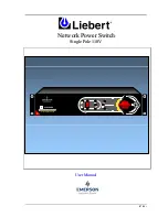
Page 31: ...Chapter 4 User Manual N Ne et tw wo or rk k P Po ow we er r S Sw wi it tc ch h 02 04 Page 5 5 ...

Reviews: