background image

www.Fisher.com

D100320X012

Types 1051 and 1052 Sizes 40, 60 and 70
Styles H and J Rotary Actuators

Contents

Introduction

3

. . . . . . . . . . . . . . . . . . . . . . . . . . . . . . . 

Scope of Manual

3

. . . . . . . . . . . . . . . . . . . . . . . . . 

Description

3

. . . . . . . . . . . . . . . . . . . . . . . . . . . . . . 

Specifications

4

. . . . . . . . . . . . . . . . . . . . . . . . . . . . 

Principle of Operation

4

. . . . . . . . . . . . . . . . . . . . . 

Installation

4

. . . . . . . . . . . . . . . . . . . . . . . . . . . . . . . . 

Actuator Mounting

4

. . . . . . . . . . . . . . . . . . . . . . . . 

Loading Connections

11

. . . . . . . . . . . . . . . . . . . . . 

Adjustment

11

. . . . . . . . . . . . . . . . . . . . . . . . . . . . . . . 

Type 1051 and 1052 Turnbuckle Adjustment 11
Type 1052 Spring Adjustment

12

. . . . . . . . . . . . . 

Initial Compression

12

. . . . . . . . . . . . . . . . . . . . . 

Stroking Range

13

. . . . . . . . . . . . . . . . . . . . . . . . 

Maintenance

13

. . . . . . . . . . . . . . . . . . . . . . . . . . . . . 

Disassembly

14

. . . . . . . . . . . . . . . . . . . . . . . . . . . . 

Assembly

16

. . . . . . . . . . . . . . . . . . . . . . . . . . . . . . . 

Changing Actuator Mounting

18

. . . . . . . . . . . . . . . 

Changing Styles

18

. . . . . . . . . . . . . . . . . . . . . . . . . 

Changing Positions

19

. . . . . . . . . . . . . . . . . . . . . . 

Top-Mounted Handwheels and 

Adjustable Travel Stops

21

. . . . . . . . . . . . . . . . . 

Handwheel and Travel Stop Operations

21

. . . . 

Handwheel and Travel Stop Maintenance

22

. . . 

For Top-Mounted Handwheels and Adjustable

Up Travel Stops

22

. . . . . . . . . . . . . . . . . . . . . . . 

For Adjustable Down Travel Stops

23

. . . . . . . . . 

Parts Ordering

23

. . . . . . . . . . . . . . . . . . . . . . . . . . . . 

Parts List

24

. . . . . . . . . . . . . . . . . . . . . . . . . . . . . . . . 

Note

Neither Emerson, Emerson Process
Management, nor any of their affiliated
entities assumes responsibility for the
selection, use and maintenance of any
product. Responsibility for the
selection, use, and maintenance of any
product remains with the purchaser
and end-user.

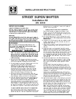
Figure 1. Type 1051 Actuator with H Mounting Adaptation 

and Type 3610J Positioner

Figure 2. Type 1052 Actuator with J Mounting Adaptation

W4252 / IL

W4139-1 / IL

Instruction Manual

Form 5587
November 2006

1051 & 1052 H & J

Summary of Contents for 1051 H

Page 1: ...and Adjustable Travel Stops 21 Handwheel and Travel Stop Operations 21 Handwheel and Travel Stop Maintenance 22 For Top Mounted Handwheels and Adjustable Up Travel Stops 22 For Adjustable Down Travel Stops 23 Parts Ordering 23 Parts List 24 Note Neither Emerson Emerson Process Management nor any of their affiliated entities assumes responsibility for the selection use and maintenance of any produc...

Page 2: ... Temperature Capabilities 3 Nitrile Diaphragm or O Rings 1 40 to 82_C 40 to 180_F Silicone Diaphragm 40 to 149_C 40 to 300_F Travel Indication Graduated disc and pointer combination located on actuator end of valve shaft Pressure Connections 1 4 in NPT female Mounting Positions See figure 10 Approximate Weights See table 7 Additional Specifications For casing pressure ranges and for material ident...

Page 3: ... rotary control valves and other equipment The Type 1051 actuator can be used for on off service or it can be used for throttling service when equipped with a valve positioner The Type 1052 actuator can be used for on off service or it can be used for throttling service when equipped with or without a valve positioner The Type 1052 actuator spring is adjustable The H mounting adaptation permits th...

Page 4: ...ssure relieving devices to prevent the diaphragm sizing pressure from exceeding the maximum allowable diaphragm sizing pressure Check with your process or safety engineer for any additional measures that must be taken to protect against process media If installing into an existing application also refer to the WARNING at the beginning of the Maintenance section in this instruction manual Top Mount...

Page 5: ... to apply a light coat of grease to the inside of the coupling before sliding it onto the shaft 4 For an actuator with an H mounting adaptation slide the actuator with the user provided mounting bracket attached into the user provided coupling on the operated shaft Then secure the actuator to the operated equipment in the desired mounting position with the appropriate fasteners such as mounting ca...

Page 6: ...76 Inch 40 13 12 19 88 23 88 2 12 4 50 6 88 2 88 60 18 62 29 50 34 50 2 50 4 75 7 31 3 00 70 1 21 12 33 44 2 50 4 75 7 31 3 00 1 Size 70 available in Type 1052 only 1 4 INCH NPT Figure 4 Type 1051 Mounting Dimensions refer to table 4 19A1465 C C0577 3 IL NOTE SEE PARTS LIST FOR WOODRUFF KEY NUMBERS 1 1 1 4 INCH NPT C DIA E E H Y F P H Y TYPE 1051 TYPE 1051 STYLE H MOUNTING ADAPTATION WOODRUFF KEY ...

Page 7: ...1 4 INCH NPT C DIA E H Y F P TYPE 1052 WOODRUFF KEY TYPE 1052 STYLE J ADAPTATION 9 5 THRU 38 1 mm 3 8 THRU 1Ć1 2ĆINCH OUTPUT SHAFTS 19A1461 D 19A1461 G 1 4 INCH NPT E H Y TYPE 1052 STYLE J MOUNTING ADAPTATION FOR 44 5 AND 50 8 mm 1Ć3 4 AND 2ĆINCH KEYED EQUIPMENT SHAFT 19A1461 D TYPE 1052 STYLE H ADAPTATION 12 7 THRU 38 1 mm 1 2 THRU 1Ć1 2ĆINCH OUTPUT SHAFTS E H Y S DIA M K N Sj L V K ...

Page 8: ... 5 16 18 UNC 40 60 40 60 28 6 1 1 8 26 2 1 03 19 1 0 75 22 10 21 97 0 870 0 865 76 2 3 00 38 1 1 50 3 8 16 UNC 40 60 40 60 70 38 1 1 1 2 28 4 1 50 28 4 1 12 28 45 28 32 1 120 1 115 88 9 3 50 44 5 1 75 1 2 13 UNC 1 Tolerance for the K dimension is indicated by showing maximum and minimum dimensions Figure 6 Type 1051 and 1052 Style H Mounting Dimensions refer to table 5 22 2 THRU 38 1 mm 7 8 THRU 1...

Page 9: ...1 2 0 44 60 70 3 31 8 1 1 4 31 75 31 80 1 250 1 252 148 5 81 68 3 2 69 30 2 1 19 210 8 25 50 8 2 00 17 5 0 69 60 70 3 38 1 1 1 2 38 13 38 18 1 501 1 503 148 5 81 68 3 2 69 23 9 0 94 210 8 25 50 8 2 00 17 5 0 69 60 70 3 50 8 1 3 4 2 44 45 44 50 1 750 1 752 123 4 84 69 9 2 75 88 9 3 50 44 5 1 75 1 2 13 UNC 1 2 13 UNC 60 70 3 50 8 2 50 83 50 90 2 001 2 004 123 4 84 69 9 2 75 88 9 3 50 44 5 1 75 1 2 1...

Page 10: ... For actuators with J mounting 2 For conventional disc valve bodies use either valve shaft keyway 3 See figure 10 for reference coupling orientation to use with this table 4 When viewed from actuator side of valve body 5 For 60 degree rotation with PDTC action the coupling and actuator output shaft assembly will be offset 30 degrees clockwise for actuator housing construction style B or counterclo...

Page 11: ...ly be made at the factory 3 When the actuator is completely installed and connected to the instrument check for correct action air to open or air to close to match the controlling instrument For successful operation the actuator stem and operating shaft must move freely in response to the loading pressure change on the diaphragm Adjustment WARNING Before performing any adjustment steps follow the ...

Page 12: ...he actuator and check the new adjustment Continue this procedure until the operated equipment is in the closed position when the actuator is resting on its up travel stop Tighten locknut key 16 Stroke the actuator and tighten the left hand threaded locknut key 58 Tighten each locknut to the appropriate torque value listed in table 10 WARNING Exceeding any torque requirements could damage the actua...

Page 13: ... refer to the initial spring compression values listed in the table for keys 11 and 13 in the Parts List section Then adjust the unit according to the procedures in the Initial Compression portion of this section Maintenance Actuator parts are subject to normal wear and must be inspected and replaced as necessary The frequency of inspection and replacement depends upon the severity of service cond...

Page 14: ...loosen the lever but hitting the screw with excessive force could also damage operated parts or disrupt the centered position of a valve disc or other equipment 6 For an actuator with an H mounting adaptation and a 22 2 through 38 1 mm 7 8 through 1 1 2 inch output shaft unscrew the cap screws key 78 and remove the actuator from the operated equipment Mark the orientation of the lever key 27 with ...

Page 15: ...rs a Read and follow the warning printed on the nameplate key 56 located on the diaphragm plate key 4 b Pull the diaphragm plate key 4 and attached parts out of the actuator The spring key 11 diaphragm rod key 10 cap screw key 9 spring seat key 13 hex nut key 58 turnbuckle key 57 hex nut key 16 and rod end bearing key 17 will be attached to the diaphragm head WARNING For Type 1051 actuators the di...

Page 16: ...0 for bolting torques for actuator bolts and cap screws Exceeding any torque requirement may impair the safe operation of the actuator 2 Proceed as appropriate For Type 1051 actuators a Coat the thread of the cap screw key 9 and the tapered end of the diaphragm rod key 10 with lithium grease key 76 b Assemble the diaphragm rod spring seat key 13 spring key 11 and diaphragm plate key 4 and secure w...

Page 17: ...g plate key 22 4 For an actuator with an H mounting adaptation install the output shaft key 87 through the mounting plate key 22 and secure it with the retaining ring key 88 Then attach the mounting plate and output shaft assembly to the actuator housing key 20 with the cap screws key 23 Tighten the cap screws to the appropriate torque value listed in table 10 5 For an actuator with a J mounting a...

Page 18: ...sition the travel indicator key 37 so that the markings on the travel indicator and travel indicator scale that were made in step 3 of the Disassembly procedure are oriented correctly Then replace the cover key 33 and secure it with the cap screws and washers keys 34 and 63 If the holes in the cover and housing key 20 do not align use a regulated air source to move the actuator slightly off the up...

Page 19: ...n to close action rotate the operated equipment to the fully open position c With the operated equipment oriented correctly slide the lever onto the output shaft key 87 with the end marked in step 4 inserted first When installing the lever align the bolt holes in the lever as close as possible with the hole in the rod end bearing key 17 d Temporarily rotate the lever and output shaft until the rod...

Page 20: ... mark is located 90 degrees clockwise from the mark on the output shaft b If the new actuator position is 90 degrees or 180 degrees counterclockwise from the previous position install the lever so that its orientation mark is located either 90 degrees for 90 degrees or 180 degrees for 180 degrees counterclockwise respectively from the mark on the output shaft c Slide the lever onto the output shaf...

Page 21: ...e action is push down to open full closing can be restricted by use of the handwheel The adjustable up travel stop figure 16 limits the actuator stroke in the upward direction To make adjustments first relieve actuator loading pressure before removing the closing cap key 187 as it is a pressure retaining part Also for size 70 actuators the hex nut key 137 must be loosened Turning the stem key 133 ...

Page 22: ...ght To tighten the closing cap apply a good grade of thread sealant to the closing cap threads For ease of operation the stem key 133 figures 15 16 and 17 threads may need an occasional application of lithium grease A grease fitting key 169 figures 15 and 16 is provided for this purpose in the size 70 The size 70 may also need to have the thrust bearing key 175 figures 15 and 16 packed with lithiu...

Page 23: ...ey 133 out of the actuator stem The lower diaphragm plate key 82 can now be removed and the rest of the actuator disassembled 4 Reassemble by reversing the order of the steps you took to disassemble being sure to apply lubricant as previously mentioned and as shown by the lubrication boxes key 241 in figures 15 and 16 For size 70 handwheels or up travel stop assemblies coat the threads of the reta...

Page 24: ...r 2 Size 40 38A1213X072 Size 60 Push Down to Close 38A1213X022 Size 60 Push Down to Open 38A1213X042 Size 70 CV8010X0022 Common Parts figures 12 and 13 Note Part numbers are shown for recommended spares only For part numbers not shown contact your Emerson Process Management sales office Note The size 70 actuator is available only in Type 1052 actuators Key Description Part Number 1 Casing upper 2 ...

Page 25: ... d Size 70 28 req d 7 Screw cap Hex hd Size 40 4 req d Size 60 6 req d Size 70 10 req d 8 Travel Stop 2 req d 9 Screw cap Hex socket 10 Diaphragm Rod Key Description Part Number 11 Spring See following table 12 Spring barrel 13 Spring seat See following table 16 Nut hex 17 Bearing Rod End 18 Screw cap Hex hd 19 Nut Hex Jam 20 Housing 21 Screw Cap Hex Hd 4 req d 22 Plate mounting 23 Screw Cap Hex s...

Page 26: ...1051 1052 H J Instruction Manual Form 5587 November 2006 26 Figure 12 Type 1051 Actuator with Typical H and J Mounting Adaptations continued 59A2408 B D0299 2 ...

Page 27: ...1051 1052 H J Instruction Manual Form 5587 November 2006 27 Figure 13 Type 1052 Actuator with Typical H and J Mounting Adaptations 59A2420 A D0300 1 IL ...

Page 28: ...mber 27 Lever 28 Screw cap Hex Hd 29 Hub 30 Retaining Ring Ext 31 Bushing 2 req d Size 40 12A9373X012 Sizes 60 70 12A9374X012 33 Cover 34 Screw Cap Hex Hd Key Description Part Number 34 Stud post Steel not shown w Type 3555T 4 req d 35 Scale Indicator w out handwheel or w Type 3555T 36 Screw Self Tap 2 req d 37 Travel Indicator 38 Self Tapping Screw 2 req d 38 Machine Screw 2 req d Recommended spa...

Page 29: ...2 mm 7 8 inch Actuator output shaft 12A9557X012 w 28 6 mm 1 1 8 inch Actuator output shaft 12A9775X012 w 38 1 mm 1 1 2 inch Actuator output shaft 12A9559X012 Key Description Part Number 67 Bushing PTFE continued Style J Mounting Size 40 w 9 5 12 7 mm 3 8 1 2 inch Actuator output shaft 12A9555X012 w 15 9 mm 5 8 inch output shaft 12A9555X012 Sizes 40 60 w 19 1 25 4 mm 3 4 1 inch Actuator output shaf...

Page 30: ...Size 60 w 19 1 mm 3 4 inch actuator output shaft 4 req d w 25 4 mm 1 inch actuator output shaft 4 req d w 31 8 mm 1 1 4 inch actuator output shaft 4 req d w 38 1 mm 1 1 2 inch actuator output shaft 4 req d w 50 4 mm 2 inch actuator output shaft for 44 5 mm 1 3 4 inch keyed equipment shaft 1 req d for 50 4 mm 2 inch keyed equipment shaft 1 req d Key Description Part Number 82 Diaphragm head lower T...

Page 31: ...igure 15 51 Handwheel 54 Hex Nut Slotted 133 Stem 135 Plate Pusher 137 Hex Nut Jam Steel 138 O Ring Nitrile Size 40 1D237506992 Size 60 1B885506992 Size 70 1C415706992 Key Description Part Number 139 O Ring Nitrile Size 40 1D267306992 Size 60 1D547106992 Size 70 1D269106992 140 Groove Pin Sizes 40 60 141 Cap Screw Hex hd Size 40 6 req d Size 60 8 req d Size 70 12 req d 142 Body 164 Body Extension ...

Page 32: ...vel stop cap Size 70 241 Lithium Grease not furnished w travel stop 242 Thread Locking Adhesive High Strength not furnished w travel stop Type 1052 Size 70 only Key Description Part Number Adjustable Down Travel Stop figure 17 54 Hex Nut Type 1051 Size 40 1 req d Size 60 2 req d Type 1052 Size 40 1 req d Sizes 60 70 2 req d 63 Flange Nut Sizes 40 70 133 Travel Stop Stem 134 Washer Plain 139 O Ring...

Page 33: ...162827082 1P270227042 70 0 7 10 1 0 2 3 0 1R676027042 30 0 3 0 3 3 7 3 9 0 3 0 2 0 2 3 7 3 0 3 0 1F177027092 1F171127092 1F177227092 0 to 2 8 0 to 40 40 0 3 0 4 4 4 6 0 0 2 3 0 3 0 1N844027082 1L217327042 60 0 5 0 5 6 8 7 0 0 2 3 0 3 1 1P270227042 1K16287082 70 0 7 10 1 0 2 3 3 1R676027082 30 0 2 3 1 0 2 3 1 1F177227092 0 to 3 8 0 to 55 40 0 3 4 4 0 2 3 5 1N844027082 0 to 3 8 0 to 55 70 0 7 10 1 0...

Page 34: ... 0 to 55 40 1L217327042 12A9446X012 0 2 to 1 0 3 to 15 60 1K162727082 12A9450X012 30 1N751527032 12A9445X012 0 2 to 2 1 3 to 30 40 1L217327042 1P637127082 12A9446X012 12A9447X012 0 2 to 2 1 3 to 30 60 1K612827082 1N937327082 12A9449X012 12A9449X012 1 For more detailed ordering information concerning proper spring and spring seat selection to obtain the torque required by the valve contact your Eme...

Page 35: ...ber 2006 35 Figure 16 Adjustable Up Travel Stops 28A1207 B DOC 28A1214 A DOC CV8057 D DOC ADJUSTABLE UP TRAVEL STOP FOR SIZE 30 AND 40 ACTUATORS ADJUSTABLE UP TRAVEL STOP FOR SIZE 60 ACTUATORS ADJUSTABLE UP TRAVEL STOP FOR SIZE 70 TYPE 1052 ACTUATORS ...

Page 36: ...their use or applicability We reserve the right to modify or improve the designs or specifications of such products at any time without notice Neither Emerson Emerson Process Management nor any of their affiliated entities assumes responsibility for the selection use and maintenance of any product Responsibility for the selection use and maintenance of any product remains with the purchaser and en...

Reviews: