Electrolux EWM09312, Service Manual
The Electrolux EWM09312 is a high-quality washing machine designed to provide exceptional performance and convenience. With its wide range of features and advanced technology, this appliance ensures efficient and effective laundry care. For a hassle-free experience, you can easily access the service manual by downloading it for free from manualshive.com.
Share
Download


Reviews:
No comments
Related manuals for EWM09312

266
Brand: V-ZUG Pages: 12
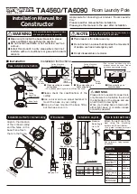
TA4560
Brand: TAKARA Pages: 2
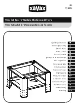
00110229
Brand: Xavax Pages: 12
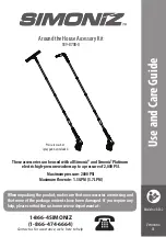
039-8708-0
Brand: Simoniz Pages: 8
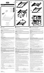
111363
Brand: Xavax Pages: 2
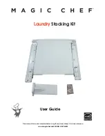
MCSLRW
Brand: Magic Chef Pages: 6
EDS
Brand: Electrolux Pages: 40
EPWD15T
Brand: Electrolux Pages: 12
137147600 B (0906)
Brand: Frigidaire Pages: 20
137147900 A
Brand: Frigidaire Pages: 16
FAM155R1AA
Brand: Frigidaire Pages: 12
FDPW1
Brand: Frigidaire Pages: 3
49-90233
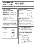
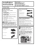
Brand: GE Pages: 12
49-90321
Brand: GE Pages: 36
49-90344
Brand: GE Pages: 12
DPVH8800GJ
Brand: GE Pages: 12
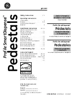
Profile SmartDispense SPBD880
Brand: GE Pages: 64
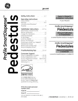
Profile SmartDispense SPBD880
Brand: GE Pages: 64


