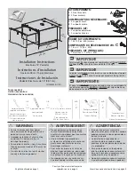
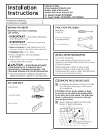
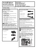
Electrolux EDS, Installation Manual
The Electrolux EDS Installation Manual is a comprehensive guide that provides step-by-step instructions for setting up and utilizing your appliance effectively. This invaluable manual can be downloaded for free from manualshive.com, ensuring you have all the necessary information at your fingertips to optimize your Electrolux EDS experience.
Share
Download


Reviews:
No comments
Related manuals for EDS

266
Brand: V-ZUG Pages: 12
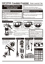
TA4560
Brand: TAKARA Pages: 2
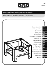
00110229
Brand: Xavax Pages: 12

039-8708-0
Brand: Simoniz Pages: 8
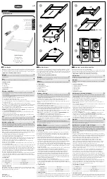
111363
Brand: Xavax Pages: 2
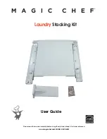
MCSLRW
Brand: Magic Chef Pages: 6
EPWD15T
Brand: Electrolux Pages: 12
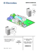
EWM09312
Brand: Electrolux Pages: 70
137147600 B (0906)
Brand: Frigidaire Pages: 20
137147900 A
Brand: Frigidaire Pages: 16
FAM155R1AA
Brand: Frigidaire Pages: 12
FDPW1
Brand: Frigidaire Pages: 3
49-90233
Brand: GE Pages: 12
49-90321
Brand: GE Pages: 36
49-90344
Brand: GE Pages: 12
DPVH8800GJ
Brand: GE Pages: 12
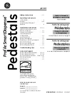
Profile SmartDispense SPBD880
Brand: GE Pages: 64
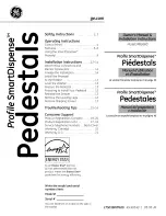
Profile SmartDispense SPBD880
Brand: GE Pages: 64


