


Summary of Contents for E15TC75HPS - Fully Integrated Trash Compactor
Page 1: ...Publication 5995530945 December 2008 Technical Service Manual Trash Compactor ...
Page 42: ...42 Notes ...
Page 43: ...43 Notes ...
Page 44: ......
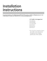
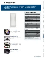
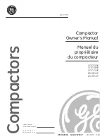
The Electrolux E15TC75HPS - Fully Integrated Trash Compactor is a top-of-the-line appliance designed to streamline waste management in your kitchen. For convenient troubleshooting and maintenance, make sure to download the free Technical & Service Manual from manualshive.com. This comprehensive manual will provide you with all the necessary information to keep your compactor running smoothly.
Page 1: ...Publication 5995530945 December 2008 Technical Service Manual Trash Compactor ...
Page 42: ...42 Notes ...
Page 43: ...43 Notes ...
Page 44: ......