background image

CHDI 8610

Cooker Hood

Operating and Installation Instructions

Summary of Contents for CHDI 8610

Page 1: ...CHDI 8610 Cooker Hood Operating and Installation Instructions ...

Page 2: ...etting the saturation indicator 8 Maintenance and care 9 Cleaning the hood 9 Metal grease filter 9 Removing the metal grease filter 9 Charcoal filter 10 Changing the light bulb 11 What to do if 12 Service and Spare Parts 13 Guarantee Conditions 14 Technical Specifications 16 Mounting accessories included 16 Electrical connection 16 Safety warnings for the electrician 16 Installation 17 Printed on ...

Page 3: ...matic circuit breaker It is very important to clean the hood and replace the filter at the recommended intervals Failure to do so could cause grease deposits to build up resulting in a fire hazard For the Installer When used as an extractor unit the hood must be fitted with a 150mm diameter hose Should there already be a pipe of diameter 125 mm that ducts to the outside through the walls or roof i...

Page 4: ...rge to avoid the possibility of a depression being created during operation of the hood If you have any doubts contact the relevant controlling authority or building inspector s office Since the rule for rooms with fuel burning appliances is outlet hole of the same size as the ventilation hole a hole of 500 600 cm2 which is to say a larger hole could reduce the performance of the extractor hood If...

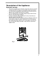
Page 5: ...ce Centre The air is discharged to the outside through a pipe which must be fitted to connection flange A Fig 1 In order to obtain the best performance the hose should have a diameter equal to the outlet hole For the extractor version this pipe must have a diameter of 150 mm Should there already be a pipe of diameter 125 mm that ducts to the outside through the walls or roof it is possible to use ...

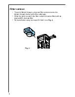
Page 6: ... a charcoal filter and returned to the kitchen through the top grill of the outlet pipe When the hood is used in the filter version it must be fitted with an original AEG charcoal filter Fix the deflector using 4 screws Ø 3 5x6 5 mm Fig 2 F Fig 2 ...

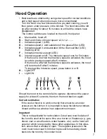
Page 7: ...s to previous speed after 5 minutes If the hood is off when the Intensive speed is activated the hood will be turned off after 5 minutes To interrupt the Intensive speed press button A or B H Light OFF I Light ON Should the hood or the controls fail to operate disconnect the power supply for at least 5 seconds then turn the hood back on again Correct ventilation If the cooker hood is to work corre...

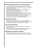
Page 8: ... the saturation indicator will be enabled To disable it Press buttons B and G again simultaneously and hold them for 3 seconds until the charcoal filter LED goes out Grease filter LED D LED D will start to flash when it is time to clean the grease filter Cleaning will be necessary after 40 working hours Always comply with the maintenance instructions for the grease filter see page 9 Charcoal filte...

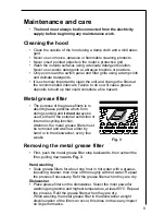
Page 9: ...the grease filters is to absorb grease particles which form during cooking and it must always be used either in the external extraction or internal recycling function Attention the metal grease filters must be removed and washed either by hand or in the dishwasher every four weeks Removing the metal grease filter First push the metal grease filter stop backwards then extract the filter pulling dow...

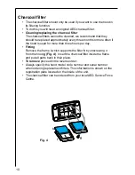
Page 10: ... if the hood is used for more than three hours per day Fitting Remove the frame i which supports the filter h by unscrewing it from the hood g Fig 4 Insert the charcoal filter inside the frame and put all parts back in their place To remove proceed in the reverse order Always specify the hood model code number and serial number when ordering replacement filters This information is shown on the reg...

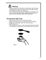
Page 11: ...tor or any fire damage linked to inappropriate maintenance or failure to observe the above safety recommendations Changing the light bulb Disconnect the cooker hood from the mains supply Remove the lamp cover use a screw driver as a lever Fig 5 Replace the old bulb with a new one of the same type Refit the lamp cover If the light does not come on make sure the bulb has been inserted in correctly b...

Page 12: ...ction check that the ducting and outlets are not blocked The cooker hood has switched off The safety cut out device has been during operation tripped Turn off the hob and then wait for the device to reset If the hood has been installed below the heights indicated in the installation instructions the motor will cut out frequently which will damage the hood If after all these checks the problem pers...

Page 13: ...Please note that proof of purchase is required for in guarantee service calls Help us to help you Please determine your type of enquiry before writing or telephoning When you contact us we need to know Your name Address and post code Telephone number Clear and concise details of the fault Name and model of the appliance E number This information can be found on the rating plate which can be seen w...

Page 14: ...EG reserves the right to stipulate the place of the repair i e the customer s home place of installation or AEG workshop 4 The guarantee or free replacement includes both labour and materials 5 Repairs carried out under guarantee do not extend the guarantee period for the appliance Parts removed during guarantee repairs become the property of AEG 6 The purchaser s statutory rights are not affected...

Page 15: ... of your new home They will then ensure that the local Service Organisation is aware of your move and able to look after you and your appliances France Senlis 33 0 44 62 29 29 Germany Nürnberg 49 0 800 234 7378 Italy Pordenone 39 0 800 117 511 Sweden Stockholm 46 0 8 672 5360 UK Slough 44 0 1753 219899 ...

Page 16: ...y The hood has a power cable 150 cm with earth connection and the rated voltage is 220 240 V Connect the hood to the mains supply via a double pole switch which has 3 mm minimum separation between the contacts The switch must be accessible at all times The following is valid in the United Kingdom only the wire which is coloured green and yellow must be connected to the terminal which is marked wit...

Page 17: ...am with the wording FRONT corresponds to the control panel side Prepare the electrical connection Drill as shown 6 holes for 6 wall plugs 4 plugs for fixture screw the outer screws leaving a space of about 1 cm between the screw head and the ceiling 4 Fit an exhaust pipe inside the support 5 and connect it to the motor compartment connection ring exhaust pipe and fixing brackets are not supplied H...

Page 18: ...18 2a 3 4 4 4 4 4 4 6 6 7 7 7 7 8 8 2a 5 7 9 10 10 10 10 11 11 14 5 273 273 244 214 190 6 12 2b 2b Fig 6 ...

Page 19: ...4 supplied inside the top and bottom sections of the flues at the rectangular slots A total of 10 nuts must be fitted Join the two top sections of the flue to cover the support 15 so that one of the slots on the sections is situated on the same side of the control panel and the other on the opposite side Screw the two sections together with 4 screws 2 each side see the plan diagram for joining the...

Page 20: ...20 15 15 15 15 15 16 16 15 15 13F F 13A 15 14 Fig 7 ...

Page 21: ... so that it completely covers the motor compartment and electrical connection box then ensure it from inside the hood using two screws 19 Apply the 2 tabs 20 supplied to cover the fixing points of the bottom flue CAUTION THE BOTTOM FLUE TABS ARE THE NARROWER AND SHALLOWER ONES The wider and deeper tabs are those used for the top flue and must be cut to size Turn the mains power on again at the cen...

Page 22: ...22 19 18 18 18 18 18 18 18 18 18 18 M X 17 17 19 20 X 20 Fig 8 ...

Page 23: ...23 ...

Page 24: ...AEG Hausgeräte GmbH Postfach 1036 D 90327 Nürnberg http www aeg hausgeraete de Copyright by AEG LI1WXB Ed 04 02 ...

Reviews: