Electrolux Afuera, Planning & Installation Manual
The Electrolux Afuera, an innovative outdoor appliance, brings convenience and functionality to your outdoor space. Take control of your cooking experience with step-by-step guidance provided in the detailed Owner's Manual. Download the manual for free from our website and unlock the full potential of this exceptional product.
Share
Download


Reviews:
No comments
Related manuals for Afuera

MX2500
Brand: H-P Products Pages: 12

Vac 1.6
Brand: SACH Pages: 99

59132-297
Brand: Hoover Pages: 12
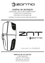
ZNT 140 M
Brand: ZANTIA Pages: 12
1300 L
Brand: Aenera Pages: 40
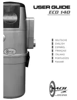
ECO 140
Brand: SACH Pages: 60
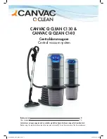
QCLEAN C130
Brand: CANVAC Pages: 24
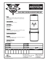
AKCVQZ99
Brand: Air King Pages: 1
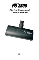
PowerSweep PS 2800
Brand: H-P Products Pages: 4
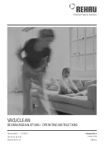
VACUCLEAN
Brand: Rehau Pages: 40
AKCV30
Brand: Air King Pages: 4
3400.20
Brand: TECNOPLUS Pages: 96
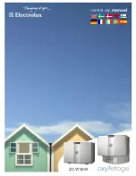
Oxy3etage
Brand: Electrolux Pages: 40
WP112K
Brand: VacuMaid Pages: 4

Signature XLS970
Brand: Cana-Vac Pages: 16
A900
Brand: InterVac Pages: 4

ECO
Brand: Husky Pages: 8
Electra
Brand: CVTECH Pages: 53


