Electrolux 7000, Service Manual
The Sealey 7000 is a top-of-the-line tool with an array of features, designed to make your jobs easier. To ensure proper use, we offer an Instructions Manual that you can download for free at manualshive.com, providing a comprehensive guide for maximizing the benefits and functionality of your Sealey 7000.
Share
Download


Reviews:
No comments
Related manuals for 7000
100 Series
Brand: La San Marco Pages: 24
CM300
Brand: Barista Mate Pages: 12
682
Brand: National Vendors Pages: 42
TAS 40xx
Brand: Tassimo Pages: 14
HDC300
Brand: Hamilton Beach Commercial Pages: 12
Erika 3.1
Brand: Havso Pages: 24
Duet
Brand: UFESA Pages: 58
40792
Brand: Hamilton Beach Pages: 56

CM200
Brand: Barista Mate Pages: 14
M220
Brand: MAGIMIX Pages: 7
M190
Brand: MAGIMIX Pages: 46
S14
Brand: Caffitaly System Pages: 2
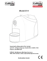
S14
Brand: Caffitaly System Pages: 12
V1.0
Brand: La Marzocco Pages: 64
Mirage
Brand: Kees van der Westen Pages: 66
E71
Brand: Faema Pages: 328
NC-ZF1
Brand: Panasonic Pages: 44
Exprelia Evo HD8855
Brand: Saeco Pages: 80


