24
CONTENTS
I.
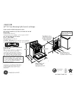
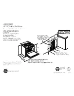
INSTALLATION DIAGRAM / JOINING APPLIANCES / TABLES ............................................................................................. 2
II. DATAPLATE and TECHNICAL DATA ......................................................................................................................................... 25
III. GENERAL INSTRUCTIONS ....................................................................................................................................................... 26
IV. THE ENVIRONMENT .................................................................................................................................................................. 27
1.
PACKING .................................................................................................................................................................................... 27
2.
USE
.................................................................................................................................................................................... 27
3.
CLEANING ................................................................................................................................................................................... 27
4.
DISPOSAL ................................................................................................................................................................................... 27
V. INSTALLATION ........................................................................................................................................................................... 27
1.
REFERENCE STANDARDS ........................................................................................................................................................ 27
2.
UNPACKING ................................................................................................................................................................................ 27
3.
POSITIONING .............................................................................................................................................................................. 28
4.
FUME EXHAUST AND VENTILATION ........................................................................................................................................ 28
5.
CONNECTIONS ........................................................................................................................................................................... 28
6.
BEFORE COMPLETING INSTALLATION OPERATIONS .......................................................................................................... 30
VI. USER INSTRUCTIONS ................................................................................................................................................................ 31
1.
COOKER USE ............................................................................................................................................................................. 31
2.
COOKER WITHOUT THERMOCOUPLE .................................................................................................................................... 31
3.
COOKER WITH THERMOCOUPLE ............................................................................................................................................ 31
4.
SWITCHING THE OVEN ON ....................................................................................................................................................... 32
VII. CLEANING .................................................................................................................................................................................. 32
1.
EXTERNAL PARTS ...................................................................................................................................................................... 32
2.
IDLE PERIODS ............................................................................................................................................................................ 33
3.
INTERNAL PARTS ....................................................................................................................................................................... 33
VIII. MAINTENANCE .......................................................................................................................................................................... 33
1.
MAINTENANCE ........................................................................................................................................................................... 33


