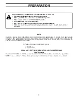
background image

WA

RN

IN

G

Do

no

t o

pe

rat

e m

owe

r u

nle

ss

co

nta

ine

r is

pro

pe

rlyi

ss

ub

ject

to

we

ar

an

d d

eti

eri

ora

tio

n.

Ch

ec

k b

ag

fre

qu

en

tly.

Re

pla

ce

wh

en

cra

cke

d o

r d

am

ag

ed

. U

se

on

ly

a r

ec

om

me

nd

ed

rep

lace

me

nt

co

nta

ine

r.

WA

RN

IN

G

Do

no

t o

pe

rat

e m

owe

r u

nle

ss

co

nta

ine

r is

pro

pe

rly

issu

bje

ct

to

we

ar

an

d d

eti

erio

rat

ion

. C

he

ck

ba

g f

req

ue

ntl

y. R

ep

lace

wh

en

cra

cke

d o

r d

am

ag

ed

. U

se

on

ly

a r

ec

om

me

nd

ed

rep

lace

me

nt

co

nta

ine

r.

WA

RN

IN

G

Do

no

t o

pe

rat

e m

owe

r u

nle

ss

co

nta

ine

r is

pro

pe

rlyi

ssu

bje

ct

to

we

ar

an

d d

eti

eri

ora

tio

n.

Ch

eck

ba

g f

req

ue

ntl

y. R

ep

lace

wh

en

cra

cke

d o

r d

ama

ge

d.

Use

on

ly

a r

eco

mm

en

de

d r

ep

lace

me

nt

co

nta

ine

r.

02079

•     Assembly
•     Operation
•     Customer Responsibilities
•     Repair Parts

156239  Rev. 5  5.19.03   rad

OWNER’S MANUAL
Model No. CL46B
Product No. 954 04 06-06
46 Inch Mower 
Grass Catcher

Printed in U.S.A.

Summary of Contents for 156239

Page 1: ...n Ch eck ba g fre qu en tly Re pla ce wh en cra cked or da ma ge d Us e on ly a recomm en de d repla ceme nt conta ine r WARNING Do no t op erate mo we r un les s conta ine r is prop erlyissub jec t to we ar an d de tierio ration Ch eck ba g fre qu en tly Re pla ce wh en cra cked or da ma ge d Us e on ly a recomm en de d repla ceme nt conta ine r 02079 Assembly Operation Customer Responsibilities ...

Page 2: ...ges in speed or direction Avoid starting or stopping on a slope If tires lose traction disengage the blades and proceed slowly straight down the slope Safe Operation Practices for Ride On Mowers IMPORTANT THIS CUTTING MACHINE IS CAPABLE OF AMPUTATING HANDS AND FEET AND THROWING OBJECTS FAILURE TO OBSERVE THE FOLLOWING SAFETY INSTRUCTIONS COULD RESULT IN SERIOUS INJURY OR DEATH SAFETY RULES DO NOT ...

Page 3: ...look down and behind before and while backing Never carry children They may fall off and be seriously injured or interfere with safe machine operation Keepchildrenoutofthemowingareaandunderthewatchful care of another responsible adult Be alert and turn machine off if children enter the area Before and when backing look behind and down for small children Mow up and down slopes 15 Max not across Rem...

Page 4: ...om carton Foldflapstoinsideofcartonandturncartonupsidedown on floor of work area To protect grass catcher cover duringassemblyplacecoverupsidedownonoverturned carton Check carton contents against list Be sure all parts are there CARTON CONTENTS 3 Container Tops 3 Container Bottoms 1 Upper Chute 1 Lower Chute 1 Support Post 1 Support Tube NOTE For ease of assembly aside of your work area lay out al...

Page 5: ...GROUP G CHUTE LATCH ASSEMBLY to LOWER CHUTE 2 Nut Weld 10 2 Washer Lock 10 2 Washer 3 16 x 3 4 x 16 Ga 2 Screw 10 x 5 8 2 Latch Hook Assembly 1 Nut Weld 10 1 Washer Lock 10 1 Washer 3 16 x 3 4 x 16 Ga 1 Screw 10 x 5 8 GROUP D SUPPORT POST TO MOUNTING BRACKET 1 Bracket Support Pin 1 Retainer Spring 4 Tubing End Caps GROUP E SUPPORT TUBE TO COVER ASSEMBLY 1 Bolt 5 16 18 x 3 4 2 Locknut 5 16 18 1 Bol...

Page 6: ...ng parts have completely stopped Disconnect spark plug wire from spark plug and place wire where it cannot come in contact with plug 1 3 8 Wrench 1 1 2 Wrench 2 9 16 Wrenches 1 1 2 Socket 1 Drive Ratchet 1 3 or longer Extension 1 Short Handle Phillips Screwdriver THESE ARE THE TOOLS YOU WILL NEED TO ASSEMBLE YOUR GRASS CATCHER NOTE When right hand R H and left hand L H are mentioned in this manual...

Page 7: ...sbottom on the bolts 3 Assemble the support tube to drawbar as shown From backside of drawbar place reinforcement plate so that weld screws go through holes in left side of drawbar Place support tube over weld screws and assemble flat washer lockwasher and wing nut as shown Do not tighten at this time 4 Discard remaining hex bolts and locknuts in hardware GROUP A LANCED TABS TOWARD BOTTOM SHOULDER...

Page 8: ... allow assembly to be mounted 2 With cover closed lift assembly and place support post inside mounting bracket Allow assembly to rest on lanced tabs of mounting bracket 3 Line up holes in mounting bracket with holes in support postandinsertbracketsupportpin Securewithretainer spring 4 Unlatch and open cover 5 Secure cover assembly to support tube using short hex bolt long hex bolt and locknuts as ...

Page 9: ...tom half inside of top half as shown 2 Place one foot inside bottom half and lift top half to meet bottom half 3 Press halves tightly together while lifting top to lock into place as shown IMPORTANT BEFORELOCKINGTHETABS HOOKEDEDGES ONBOTHHALVESMUSTOVERLAPTOFORMSEALASSHOWN IN INSET 4 Repeat for other containers PRESS TOGETHER TO FORM SEAL WHILE LIFTING TOP HALF 02089 CONTAINER BOTTOM HALF CONTAINER...

Page 10: ...ver rear of mower deck opening Push chute down and forward to guide extended edge of chute between discharge guard and mower deck 5 Hook front latch into tab hole on front of mower deck 6 Hook rear latch into flange hole on back of mower deck 7 CAUTION Do not remove discharge guardfrommower Raiseandholdguard when attaching lower chute and allow it to rest on chute while in operation FIG 7A 0 2 0 9...

Page 11: ...wer chute with alignment slots on upper chute and slide together 5 Secure with rubber latch by hooking hole in latch over latch pin 10 CHUTE LATCH ASSEMBLY See Fig 8 Use Hardware GROUP F G 1 Assemble hardware shown latch pin to upper chute 2 Press weld nut into rubber latch and assemble rubber latch to lower chute as shown 3 Tighten all hardware securely 0 2 1 0 2 UPPER CHUTE LOCK WASHER WELD NUT ...

Page 12: ... container at center supports j Closecoverandsecurelatchesovercentersupport tubes Avoid cutting wet grass or in the morning while the dew is still heavy Grass clippings collected under these conditions tend to be sticky and adhere to the walls of the flow path causing clogging Your bagger is equipped with a dump bag indicator As the bags become full the flow indicating ball will drop down in its s...

Page 13: ...or damaged blades See BLADE CARE instructions in your tractor owner s manual CAUTION BEFOREPERFORMINGANY MAINTENANCE SERVICEORADJUST MENTS Depress clutch brake pedal fully and set parking brake Place gearshift motion control lever in NEUTRAL position Placeclutchcontrolin DISENGAGED position Turn ignition key to OFF position Make sure blades and all moving parts have completely stopped Disconnect s...

Page 14: ...OME MODEL TRACTORS MINOR MODIFICATIONS MAY BE NECESSARY TO MOUNT YOUR NEW GRASS CATCHER NOT ALL MODEL TRACTORS WILL NEED THE FOLLOWING MODIFICATIONS CHECK EACH STEP CAREFULLY TO DETERMINE IF MODIFICATION IS REQUIRED ONCE YOUR MODEL TRACTOR CONFORMS TO THIS SECTION PROCEED TO ASSEMBLY DRILL SUPPORT TUBE MOUNTING HOLES IN DRAWBAR See Template On some model tractors two 7 16 holes must be drilled in ...

Page 15: ... DRILL TWO 7 16 HOLES 1 CUT OUT TEMPLATE 2 ALIGN BOTTOM AND LEFT EDGE OF TEMPLATE AND DRAWBAR 3 TAPE IN POSITION 4 MARK AND DRILL 7 16 HOLES NOTE DRILL SMALLER PILOT HOLES PRIOR TO DRILLING 7 16 HOLES 5 PROCEED WITH STEP 1 OF ASSEMBLY INSTRUCTIONS ...

Page 16: ...16 NOTES ...

Page 17: ...17 NOTES ...

Page 18: ... que ntly Re pla ce wh en cra cke d or dam age d Us e onl y a rec om me nde d rep lac em ent con tain er 2 3 4 20 2 35 20 37 2 34 33 20 25 20 9 12 13 14 18 5 8 9 9 10 11 24 32 47 47 30 26 25 28 27 27 26 36 25 20 9 12 16 15 15 16 14 40 40 40 2 2 39 29 29 6 7 WAR NING Do not ope rat e mo we r unl ess con tain er is pro per lyis nst alle d C ont ain er is sub jec t to we ar and det ieri ora tion Ch e...

Page 19: ...oulon H 5 16 18 x 2 1 4 47 872110506 Carriage Bolt 5 16 18 x 3 4 Boulon de chariot 5 16 18 x 3 4 532156239 Owner s Manual Manuel de propriétaire 2 532069180 Nut Crownlock 10 24 Écrou auto serrant 10 24 3 532127533 Screen Cover Écran de couvercle 4 532139850 Cover Assembly Couvercle Includes 3 37 38 39 Y compris 3 37 38 39 5 532126840 Chute Upper Glissière supérieure 6 818021008 Screw Special 10 14...

Reviews: