


Serious injury or death can occur from the rack tipping over. To prevent this, the rack
must be secured to a wall, especially in earthquake -prone areas, or where surfaces are uneven, and where
children and/or pets are present.
Different wall materials require different types of fasteners. Use fasteners suitable for your specific type of
wall. If you are uncertain about what type of fastener to use, then please contact your local hardware store.
If you have questions or comments, contact us.
Pour toute question ou tout commentaire, nous contacter
.
Si tiene dudas o comentarios, contáctenos.
1-844-377-8451 • www
.dewalt.com
INSTRUCTION MANUAL
GUIDE D’UTILISA
TION
MANUAL DE INSTRUCCIONES
INSTRUCTIVO DE OPERACIÓN, CENTROS DE SER
VICIO Y PÓLIZA
DE GARANTÍA.
ADVER
TENCIA:
LÉASE ESTE INSTRUCTIVO ANTES
DE USAR EL PRODUCTO.
DXST6000WB
4-Shelf Industrial Storage Rack Work Station
Composants tiroir support de fil électrique panneau perforé outil organisateurs
Estación de trabajo de estantería para almacenamiento industrial de 4 estantes
Copyright © 2018 D
E
WALT.
D
E
WALT
®
and the D
E
WALT Logo are trademarks of the D
E
WALT Industrial Tool Co., or an affiliate thereof
and are used under license. The yellow/black color scheme is a trademark for D
E
WALT
power tools & accessories.
JS PRODUCTS | 6445 MONTESSOURI STREET, LAS VEGAS, NV 89113
SAVE THESE INSTRUCTIONS
TECHNICAL SPECIFICATIONS
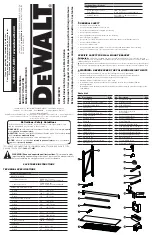
Parts List
IF YOU HAVE ANY QUESTIONS OR COMMENTS ABOUT THIS OR ANY D
E
WALT TOOL,
CALL US TOLL FREE AT:
1-844-377-8451
WARNING! Read and understand all instructions.
This manual contains
important safety and operating instructions.
Please read this manual carefully
before assembling this storage rack and save it for reference.
Technical Specifications
INDUSTRIAL RACK
Total Rack Capacity
6,000 lb (2,721.6 kg)
*when weight is evenly distributed
Capacity per Shelf
1,500 lb (680 kg)
*when weight is evenly distributed
HORIZONTAL WORK STATION
Height
47" (119.4 cm)
Width
149.5" (379.7 cm)
Depth
18" (45.72 cm)
VERTICAL WORK STATION
Height
94" (238.8 cm)
Width
49.5" (125.73 cm)
Depth
18" (45.72 cm)
DRAWER KIT
Height
6.21" (15.77 cm)
Width
42.95" (109.09 cm)
Depth
16.86" (42.82 cm)
Drawer Capacity
120 lb (54.43 kg)
PEGBOARD
Height
18" (45.72 cm)
Width
47" (119.4 cm)
No. Description
Qty.
1
Vertical Beam
4
2
Pre-Bolted Vertical Assembly
4
3
Vertical Assembly Bolt
8
4
Crossbeam
8
5
Shelf Support Strap
12
6
Safety Strap With Weld Nut
8
7
Safety Strap Bolt
16
8
Laminate Deck
2
9
Wire Grid
2
10
Locking Pin
41
11
Carriage Bolt
4
12
10 mm Nut
4
13
10 mm Wrench
1
14
4 mm Hex Key
1
15
4 mm Hex Bit
1
16
Wall Mount Bracket Assembly
2
17
Stacking Plate
4
(AUG18) Part No. 41609 DXST6000WB Copyright © 2018, D
E
WALT
WARNING:
GENERAL SAFETY
SPECIFIC SAFETY FOR WALL MOUNT BRACKET
• Keep work area clean and dry.
• Use correct/recommended tools for the job.
• Never leave unattended tools plugged in or running.
• Never force a part into place.
• Wear appropriate safety apparel for the job you are doing.
• Wear safety glasses/goggles.
• Never crawl, sit, stand, or climb on the rack, pegboards, drawer, or cord minder brackets.
• Never overload the Drawer Kit.
• Do not leave drawer open.
• Keep small parts away from children. Never leave a small child unattended while assembling.
• Always use common sense – your personal safety is your responsibility.
Definitions: Safety Guidelines
The definitions below describe the level of severity for each signal word. Please
read the manual and pay attention to these symbols.
Indicates a potentially hazardous situation which, if not avoided,
could
result in
death or serious injury.
WARNING:
Indicates a potentially hazardous situation which, if not avoided,
may
result in
minor or moderate injury.
CAUTION:
(Used without word) Indicates a safety related message.
Indicates a practice
not related to personal injury
which, if not avoided,
may
result in
property damage.
NOTICE:
No. Description
Qty.
18
Locking Grid Clip
8
19
U-Bracket Cover
8
20
Fold Up Drawer
1
21
Drawer Pull
1
22
Mounting Bracket with
Drawer Slides
2
23
Drawer Carriage Bolts
4
24
Drawer Carriage Nut
4
25
Metal Pegboard
1
26
Pegboard Mounting Beam
2
27
Side Mounting Bracket (Right)
4
28
Side Mounting Bracket (Left)
4
29
Rear Mounting Bracket (Right)
2
30
Rear Mounting Bracket (Left)
2
31
Small Locking Pin
8
32
Cord Minder Bracket
2
33
Pegboard Tool Holders
6
Technical Specifications
CORD MINDERS
Total Capacity per 2 Piece
Cord Minder Set
50 lb (22.68 kg)
*when weight is evenly distributed
Holding Capacity
Up to 100 ft of 10/3 Heavy Duty
extension cord
NEVER EXCEED THE FOLLOWING WEIGHT LIMITS
• Maximum load for the Drawer: Up to 120 lbs. (54.43kg) when evenly distributed.
• Maximum load for each shelf: Up to 1,500 lbs. (680 kg) when weight is evenly distributed.
• It is recommended that the heaviest load be placed on the bottom shelf.
• Maximum load per Cord Minder set is 50 lb (22.6 kg).
• Immediately remove the load should there be separation between the Cord Minder and the
mounting bracket.
• Immediately remove the load should there be damage, bending or warping of the rack uprights or the
Cord Minders.
WARNING:
3
5
7
4
9
8
6
10
11
13
12
1
2
15
14
16
19
18
17


