
Serious injury or death can occur from the rack tipping over. To prevent this, the rack
must be secured to a wall, especially in earthquake -prone areas, or where surfaces are uneven, and where
children and/or pets are present.
Different wall materials require different types of fasteners. Use fasteners suitable for your specific type of
wall. If you are uncertain about what type of fastener to use, then please contact your local hardware store.
If you have questions or comments, contact us.
Pour toute question ou tout commentaire, nous contacter
.
Si tiene dudas o comentarios, contáctenos.
1-844-377-8451 • www
.dewalt.com
INSTRUCTION MANUAL
GUIDE D’UTILISA
TION
MANUAL DE INSTRUCCIONES
INSTRUCTIVO DE OPERACIÓN, CENTROS DE SER
VICIO Y PÓLIZA
DE GARANTÍA.
ADVER
TENCIA:
LÉASE ESTE INSTRUCTIVO ANTES
DE USAR EL PRODUCTO.
DXST4500-W
Industrial Rack with Wir
e Grids / 4-Foot (121.92 cm) T
all / 3-Shelf
É
ta
g
èr
e i
n
d
u
st
ri
el
le a
ve
c g
ri
lle
s d
e f
il / 1
,2
2 m (
4 p
i d
e h
au
te
u
r / 3 t
ab
let
te
s
E
st
an
te
ría i
nd
us
tr
ia
l c
on r
eja
s d
e a
la
m
br
e / 4 p
ie
s (
12
1.
92 c
m
) d
e a
ltu
ra / 3 e
st
an
te
s
Copyright © 2018 D
E
WALT.
D
E
WALT
®
and the D
E
WALT Logo are trademarks of the D
E
WALT Industrial Tool Co., or an affiliate thereof
and are used under license. The yellow/black color scheme is a trademark for D
E
WALT
power tools & accessories.
JS PRODUCTS | 6445 MONTESSOURI STREET, LAS VEGAS, NV 89113
SAVE THESE INSTRUCTIONS
READ ALL INSTRUCTIONS
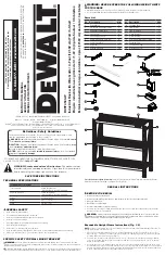
TECHNICAL SPECIFICATIONS
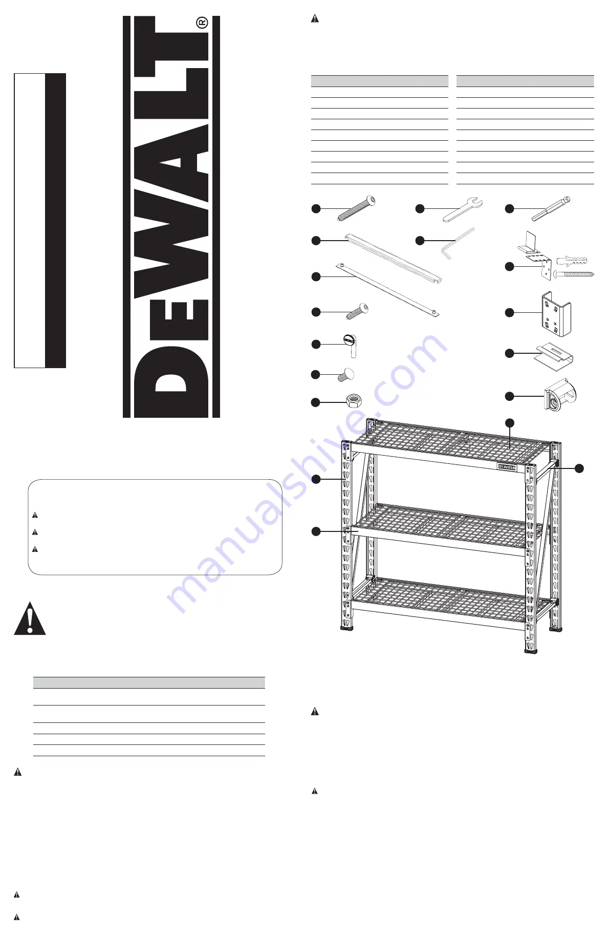
Parts List
IF YOU HAVE ANY QUESTIONS OR COMMENTS ABOUT THIS OR ANY D
E
WALT TOOL,
CALL US TOLL FREE AT:
1-844-377-8451
WARNING! Read and understand all instructions.
This manual contains
important safety and operating instructions.
Please read this manual carefully
before assembling this storage rack and save it for reference.
Technical Specifications
Total Capacity
4,500 lb (2,041 kg)
*when weight is evenly distributed
Capacity per Shelf
1,500 lb (680 kg)
*when weight is evenly distributed
Height
47" (119.4 cm)
Width
49.5" (126 cm)
Depth
18" (45.7 cm)
No. Description
Qty.
1
Vertical Beam
2
2
Pre-Bolted Vertical Assembly
2
3
Vertical Assembly Bolt
4
4
Crossbeam
6
5
Shelf Support Strap
9
6
Safety Strap With Weld Nut
6
7
Safety Strap Bolt
12
8
Wire Grid
3
9
Locking Shelf Pin
16
• Read all instructions thoroughly.
• Remove all components from the box, and lay them on the floor in an orderly fashion.
• Wear eye protection.
• Be cautious of sharp edges.
• Keep this information for further reference.
• If you are not stacking a second rack at this time, then please store the Stacking Plates for potential
future use as they will be needed.
(MAY18) Part No. 41590 DXST4500-W Copyright © 2018, D
E
WALT
WARNING:
WARNING:
Serious or fatal crushing injuries can occur from rack tipping over. To prevent this, the
assembled rack must always be secured to a wall, especially in earthquake-prone environments, where
surfaces are uneven, and where children and/or pets are present.
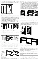
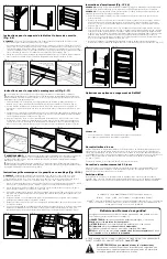
NOTE:
For ease of assembly, two (2) vertical beams feature pre-bolted horizontal and diagonal beams, as
well as pre-attached U-bracket covers.
1. Place one (1) vertical beam and one (1) pre-bolted vertical beam on the floor, parallel to one another
(about 18"/45.7 cm apart). The widest part of the teardrop-shaped hole pattern on each beam should
be facing upward (or away from you). (Fig. 1)
2. There are two versions of the U-bracket covers - an “A” side and a “B” side. Before moving forward,
cover the U-shaped brackets on the vertical beam with the covers by mirroring the covers on the pre-
bolted vertical assembly.
3. Insert the free end of the diagonal beam into the free end of the horizontal beam. Align the holes, and
insert both beams into the U-shaped bracket at the top of the opposing vertical beam. Use the included
hex key or drill bit to thread the vertical assembly bolt through the holes and into the weld nut attached
to the U-shaped bracket. Do not fully tighten the bolt yet. (Fig. 2)
Expandable Upright Frame Instructions (Fig. 1-2)
GENERAL SAFETY
NEVER EXCEED THE FOLLOWING WEIGHT LIMITS
FOR THIS RACK
SPECIFIC SAFETY FOR WALL MOUNT BRACKET
• Keep work area clean and dry.
• Use correct/recommended tools for the job.
• Never leave unattended tools plugged in or running.
• Never force a part into place.
• Wear appropriate safety apparel for the job you are doing.
• Wear safety glasses/goggles.
• Never crawl, sit, stand, or climb on the rack.
• Keep small parts away from children. Never leave a small child unattended while assembling.
• Always use common sense – your personal safety is your responsibility.
• Maximum load for each shelf: Up to 1,500 lb (680 kg) when weight is evenly distributed.
• It is recommended that the heaviest load be placed on the bottom shelf.
Definitions: Safety Guidelines
The definitions below describe the level of severity for each signal word. Please
read the manual and pay attention to these symbols.
Indicates a potentially hazardous situation which, if not avoided,
could
result in
death or serious injury.
WARNING:
Indicates a potentially hazardous situation which, if not avoided,
may
result in
minor or moderate injury.
CAUTION:
(Used without word) Indicates a safety related message.
Indicates a practice
not related to personal injury
which, if not avoided,
may
result in
property damage.
NOTICE:
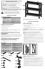
No. Description
Qty.
10
Carriage Bolt
2
11
10 mm Nut
2
12
10 mm Wrench
1
13
4 mm Hex Key
1
14
4 mm Hex Bit
1
15
Wall Mount Bracket Assembly
1
16
Stacking Plate
2
17
Locking Grid Clip
12
18
U-Bracket Cover
4
WARNING:
Tools Required for Rack Assembly:
4 mm Hex Key (included) OR 4 mm Hex Bit (included); Rubber
Mallet (not included), Flat-Head Screwdriver (not included)
3
1
4
5
7
6
9
10
15
16
17
18
2
14
8
13
12
11
BEFORE YOU BEGIN:


