background image

DWE6005-XE 

LAMINATE TRIMMER

INSTRUCTION MANUAL

Summary of Contents for DWE6005-XE

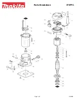
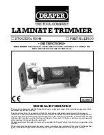
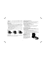
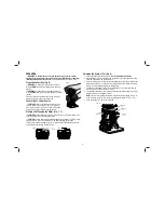
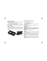
Page 1: ...DWE6005 XE LAMINATE TRIMMER INSTRUCTION MANUAL ...

Page 2: ......

Page 3: ...h ah m s2 2 5 Uncertainty K m s2 1 5 The vibration emission level given in this information sheet has been measured in accordance with a standardised test given in EN 60745 and may be used to compare one tool with another It may be used for a preliminary assessment of exposure WARNING The declared vibration emission level represents the main applications of the tool However if the tool is used for...

Page 4: ...itable for outdoor use reduces the risk of electric shock f If operating a power tool in a damp location is unavoidable use a residual current device RCD protected supply Use of an RCD reduces the risk of electric shock 3 PERSONAL SAFETY a Stay alert watch what you are doing and use common sense when operating a power tool Do not use a power tool while you are tired or under the influence of drugs...

Page 5: ...wire is required Young children and the infirm This appliance is not intended for use by young children or infirm persons without supervision This appliance is not intended for use by persons including children with reduced physical sensory or mental capabilities or lack of experience and knowledge unless they have been given supervision or instruction concerning use of the appliance by a person r...

Page 6: ...rsonal hearing protection that conforms to AS NZS1270 during use Under some conditions and duration of use noise from this product may contribute to hearing loss Check to see that the cord will not snag or impede the trimming operation Use sharp bits Dull bits may cause the laminate trimmer to swerve or stall under pressure Be sure that the bit is clear of the workpiece before starting the motor I...

Page 7: ...PM strokes per minute sfpm surface feet per minute SAVE ALL WARNINGS AND INSTRUCTIONS FOR FUTURE REFERENCE COMPONENTS FIG 1 2 WARNING Never modify the power tool or any part of it Damage or personal injury could result A Quick release tabs B Depth adjustment ring C On off switch D Spindle lock button E LED light F Guide pin groove not shown G Micro adjustment scale H Locking lever I Base J Subbase...

Page 8: ...the depth adjustment ring B is not on the motor thread the depth adjustment ring B onto the motor until the ring is positioned as shown Insert the motor into the base by aligning the groove F on the motor with the guide pins L on the base Slide the motor down until the depth adjustment ring B snaps into place 3 Adjust the depth of cut by turning the depth adjustment ring B Refer to Adjusting the D...

Page 9: ...lever is clamped the motor should not move in the base Adjustment is needed if the locking lever will not clamp without excessive force or if the motor moves in the base after clamping ADJUSTING THE LOCKING LEVER S CLAMPING FORCE 1 Open the locking lever H 2 Using a 2 5 mm hex wrench not included turn the locking lever adjustment screw M in small increments Turning the screw clockwise tightens the...

Page 10: ...nnect tool from power source before making any adjustments or removing installing attachments or accessories An accidental start up can cause injury Proper Hand Position Fig 6 WARNING To reduce the risk of serious personal injury ALWAYS use proper hand position as shown in Figure 6 WARNING To reduce the risk of serious personal injury ALWAYS hold securely in anticipation of a sudden reaction Prope...

Page 11: ... straight grain edge NOTE Make several light passes instead of one heavy pass for better quality work Troubleshooting For assistance with your tool visit our website at visit www dewalt com or call 1 800 4 DEWALT 1 800 338 002 MAINTENANCE WARNING To reduce the risk of serious personal injury turn tool off and disconnect tool from power source before making any adjustments or removing installing at...

Page 12: ... To reduce the risk of injury only DEWALT recommended accessories should be used with this product Recommended accessories for use with your tool are available at extra cost from your local service center If you need any assistance in locating any accessory please contact Stanley Black Decker 82 Taryn Drive Epping VIC 3076 Australia or call 1800 338 002 or NZ 0800 339 258 ...

Page 13: ...11 ...

Page 14: ......

Page 15: ......

Page 16: ...ewalt co nz NOV13 Part No N290040 DWE6005 XE Copyright 2013 DEWALT The following are trademarks for one or more DEWALT power tools the yellow and black color scheme the D shaped air intake grill the array of pyramids on the handgrip the kit box configuration and the array of lozenge shaped humps on the surface of the tool ...

Reviews: