background image

Inspiron 13 7000
Service Manual

Computer Model: Inspiron 13-7370
Regulatory Model: P83G
Regulatory Type: P83G001

Summary of Contents for Inspiron 13 7000 Series

Page 1: ...Inspiron 13 7000 Service Manual Computer Model Inspiron 13 7370 Regulatory Model P83G Regulatory Type P83G001 ...

Page 2: ... to hardware or loss of data and tells you how to avoid the problem WARNING A WARNING indicates a potential for property damage personal injury or death Copyright 2017 Dell Inc or its subsidiaries All rights reserved Dell EMC and other trademarks are trademarks of Dell Inc or its subsidiaries Other trademarks may be trademarks of their respective owners 2017 08 Rev A00 ...

Page 3: ... Screw list 11 After working inside your computer 13 Removing the base cover 14 Procedure 14 Replacing the base cover 17 Procedure 17 Removing the battery 18 Prerequisites 18 Procedure 18 Replacing the battery 20 Procedure 20 Post requisites 20 Removing the coin cell battery 21 Prerequisites 21 Procedure 21 3 ...

Page 4: ...g the heat sink 26 Procedure 26 Post requisites 26 Removing the fan 27 Prerequisites 27 Procedure 27 Replacing the fan 29 Procedure 29 Post requisites 29 Removing the speakers 30 Prerequisites 30 Procedure 30 Replacing the speakers 32 Procedure 32 Post requisites 32 Removing the power adapter port 33 Prerequisites 33 Procedure 33 4 ...

Page 5: ...s card 38 Procedure 38 Post requisites 39 Removing the display assembly 40 Prerequisites 40 Procedure 40 Replacing the display assembly 43 Procedure 43 Post requisites 43 Removing the I O board 44 Prerequisites 44 Procedure 44 Replacing the I O board 47 Procedure 47 Post requisites 47 Removing the solid state drive 48 Prerequisites 48 Procedure 49 5 ...

Page 6: ...ocedure 55 Post requisites 56 Removing the status light board 57 Prerequisites 57 Procedure 57 Replacing the status light board 59 Procedure 59 Post requisites 59 Removing the touchpad 60 Prerequisites 60 Procedure 60 Replacing the touchpad 63 Procedure 63 Post requisites 63 Removing the power button with fingerprint reader 64 Prerequisites 64 Procedure 64 6 ...

Page 7: ...emoving the palm rest assembly 73 Prerequisites 73 Procedure 74 Replacing the palm rest assembly 75 Procedure 75 Post requisites 76 Downloading drivers 77 Downloading the audio driver 77 Downloading the graphics driver 77 Downloading the USB 3 0 driver 78 Downloading the Wi Fi driver 78 Downloading the media card reader driver 78 Downloading the chipset driver 79 Downloading the network driver 79 ...

Page 8: ...word 91 Deleting or changing an existing system and or setup password 92 Clearing CMOS settings 93 Clearing forgotten passwords 93 Troubleshooting 94 Flashing the BIOS 94 Enhanced Pre Boot System Assessment ePSA diagnostics 94 Running the ePSA diagnostics 95 Diagnostics 95 Flea power release 97 Wi Fi power cycle 97 Getting help and contacting Dell 98 Self help resources 98 Contacting Dell 99 8 ...

Page 9: ...ard mouse and monitor from your computer 5 Remove any media card and optical disc from your computer if applicable Safety instructions Use the following safety guidelines to protect your computer from potential damage and ensure your personal safety WARNING Before working inside your computer read the safety information that shipped with your computer For more safety best practices see the Regulat...

Page 10: ...ack of the computer While you work periodically touch an unpainted metal surface to dissipate static electricity which could harm internal components CAUTION When you disconnect a cable pull on its connector or on its pull tab not on the cable itself Some cables have connectors with locking tabs or thumb screws that you must disengage before disconnecting the cable When disconnecting cables keep t...

Page 11: ...lm rest assembly M2x3 4 Fan Keyboard bracket M2x3 2 Wireless card Keyboard bracket M2x3 1 Power adapter port Palm rest assembly M2x3 1 Display assembly Palm rest assembly M2 5x5 6 I O Board Keyboard bracket M2x2 2 Power button with fingerprint reader if installed Palm rest assembly M2x2 5 2 Solid state drive Keyboard bracket M2x3 1 Type C port bracket System board M2x3 1 Palm rest assembly 1 Touch...

Page 12: ...Component Secured to Screw type Quantity Screw image System board Keyboard bracket M2x2 2 Keyboard bracket Keyboard Palm rest assembly M1 4x2 27 Keyboard Palm rest assembly M1 2x1 5 6 12 ...

Page 13: ...nsure that no stray screws remain inside your computer 2 Connect any external devices peripherals or cables you removed before working on your computer 3 Replace any media cards discs or any other parts that you removed before working on your computer 4 Connect your computer and all attached devices to their electrical outlets 5 Turn on your computer 13 ...

Page 14: ...er After working inside your computer follow the instructions in After working inside your computer For more safety best practices see the Regulatory Compliance home page at www dell com regulatory_compliance Procedure 1 Loosen the captive screw that secures the base cover to the palm rest assembly 2 Remove the nine screws M2 5x5 that secure the base cover to the palm rest assembly 14 ...

Page 15: ...3 Using a plastic scribe pry the base cover off the palm rest assembly 4 Lift the base cover off the palm rest assembly 5 Using the pull tab disconnect the battery cable from the system board 15 ...

Page 16: ...6 Turn the computer over open the display then press and hold the power button for 15 seconds to ground the system board 16 ...

Page 17: ...nside your computer For more safety best practices see the Regulatory Compliance home page at www dell com regulatory_compliance Procedure 1 Connect the battery cable to the system board 2 Align the tabs on the base cover with the slots on the palm rest assembly and snap the base cover into place 3 Replace the nine screws M2 5x5 that secure the base cover to the palm rest assembly 4 Tighten the ca...

Page 18: ...orking inside your computer follow the instructions in After working inside your computer For more safety best practices see the Regulatory Compliance home page at www dell com regulatory_compliance Prerequisites Remove the base cover Procedure 1 Remove the speaker cable from the routing guides on the battery 2 Remove the four screws M2x3 that secure the battery to the palm rest assembly 18 ...

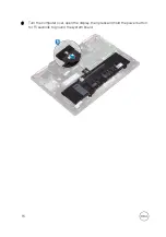
Page 19: ...3 Lift the battery off the palm rest assembly 19 ...

Page 20: ...ctions in After working inside your computer For more safety best practices see the Regulatory Compliance home page at www dell com regulatory_compliance Procedure 1 Align the screw holes on the battery with the screw holes on the palm rest assembly 2 Replace the four screws M2x3 that secure the battery to the palm rest assembly 3 Route the speaker cable through the routing guides on the battery P...

Page 21: ...ns in After working inside your computer For more safety best practices see the Regulatory Compliance home page at www dell com regulatory_compliance CAUTION Removing the coin cell battery resets the BIOS setup program s settings to default It is recommended that you note the BIOS setup program s settings before removing the coin cell battery Prerequisites Remove the base cover Procedure 1 Disconn...

Page 22: ...2 Peel the coin cell battery off the keyboard bracket 22 ...

Page 23: ... your computer After working inside your computer follow the instructions in After working inside your computer For more safety best practices see the Regulatory Compliance home page at www dell com regulatory_compliance Procedure 1 Adhere the coin cell battery to the keyboard bracket 2 Connect the coin cell battery cable to the I O board Post requisites Replace the base cover 23 ...

Page 24: ...iance home page at www dell com regulatory_compliance WARNING The heat sink may become hot during normal operation Allow sufficient time for the heat sink to cool before you touch it CAUTION For maximum cooling of the processor do not touch the heat transfer areas on the heat sink The oils in your skin can reduce the heat transfer capability of the thermal grease Prerequisites Remove the base cove...

Page 25: ...2 Lift the heat sink off the system board 25 ...

Page 26: ...ON Incorrect alignment of the heat sink can damage the system board and processor NOTE The original thermal grease can be reused if the original system board and heat sink are reinstalled together If either the system board or the heat sink is replaced use the thermal pad provided in the kit to ensure that thermal conductivity is achieved Procedure 1 Align the screw holes on the heat sink with the...

Page 27: ...ur computer For more safety best practices see the Regulatory Compliance home page at www dell com regulatory_compliance Prerequisites 1 Remove the base cover 2 Follow the procedure from step 1 to step 4 in Removing the power button with fingerprint reader if installed Procedure 1 Disconnect the fan cable from the system board 2 Remove the I O board cable from the routing guides on the fan 3 Remov...

Page 28: ...4 Lift the fan off the keyboard bracket 28 ...

Page 29: ...es see the Regulatory Compliance home page at www dell com regulatory_compliance Procedure 1 Align the screw holes on the fan with the screw holes on the keyboard bracket 2 Replace the two screws M2x3 securing the fan to the keyboard bracket 3 Route the I O board cables through the routing guides on the fan 4 Connect the fan cable to the system board Post requisites 1 Follow the procedure from ste...

Page 30: ...s in After working inside your computer For more safety best practices see the Regulatory Compliance home page at www dell com regulatory_compliance Prerequisites Remove the base cover Procedure 1 Disconnect the speaker cable from the system board 2 Lift the left speaker off the palm rest assembly 3 Remove the speaker cable from the routing guides on the battery 4 Peel off the tape that secures th...

Page 31: ...5 Lift the right speaker off the palm rest assembly 31 ...

Page 32: ... practices see the Regulatory Compliance home page at www dell com regulatory_compliance Procedure 1 Using the alignment posts align and place the right speaker on the palm rest assembly 2 Adhere the tape that secures the speaker cable to the palm rest assembly 3 Route the speaker cable through the routing guides on the battery 4 Using the alignment posts align and place the left speaker on the pa...

Page 33: ...er working inside your computer follow the instructions in After working inside your computer For more safety best practices see the Regulatory Compliance home page at www dell com regulatory_compliance Prerequisites Remove the base cover Procedure 1 Disconnect the power adapter port cable from the system board 2 Remove the screw M2x3 that secures the power adapter port to the palm rest assembly 3...

Page 34: ...3 Lift the power adapter port off the palm rest assembly 34 ...

Page 35: ...low the instructions in After working inside your computer For more safety best practices see the Regulatory Compliance home page at www dell com regulatory_compliance Procedure 1 Insert the power adapter port into the slot on the palm rest assembly 2 Replace the screw M2x3 that secures the power adapter port to the palm rest assembly 3 Connect the power adapter port cable to the system board Post...

Page 36: ...ng inside your computer After working inside your computer follow the instructions in After working inside your computer For more safety best practices see the Regulatory Compliance home page at www dell com regulatory_compliance Prerequisites Remove the base cover Procedure 1 Locate the wireless card on the I O board and then lift the Mylar from the wireless card 36 ...

Page 37: ... the wireless card bracket and wireless card to the keyboard bracket 3 Lift the wireless card bracket off the wireless card 4 Disconnect the antenna cables from the wireless card 5 Slide and remove the wireless card from the I O board 37 ...

Page 38: ... do not place any cables under it 1 Lift the Mylar to access the wireless card slot 2 Align the notch on the wireless card with the tab on the wireless card slot and insert the wireless card at an angle into the wireless card slot 3 Connect the antenna cables to the wireless card The following table provides the antenna cable color scheme for the wireless card supported by your computer Table 2 An...

Page 39: ...5 Replace the screw M2x3 that secures the wireless card to the keyboard bracket Post requisites Replace the base cover 39 ...

Page 40: ...ance home page at www dell com regulatory_compliance Prerequisites 1 Remove the base cover 2 Follow the procedure from step 1 to step 4 in Removing the wireless card Procedure NOTE The touchscreen board cable removal is only applicable for computers shipped with touchscreen configuration 1 Remove the antenna cables from the routing guides on the palm rest assembly 2 Peel off the adhesive tapes tha...

Page 41: ... the computer over and open the display as far as possible Then place the computer face down on a flat surface CAUTION Place the computer on a soft and clean surface to avoid scratching the display 6 Remove the six screws M2 5x5 that secure the display assembly to the palm rest assembly 41 ...

Page 42: ...7 Gently lift the display assembly off the palm rest assembly 42 ...

Page 43: ... the display 1 Place the display assembly on the palm rest assembly 2 Align the screw holes on the display assembly with the screw holes on the palm rest assembly 3 Replace the six screws M2 5x5 that secure the display assembly to the palm rest assembly 4 Close the display and turn the computer over 5 Slide the display cable and touchscreen board cable into their slots and then close the latches t...

Page 44: ...side your computer follow the instructions in After working inside your computer For more safety best practices see the Regulatory Compliance home page at www dell com regulatory_compliance Prerequisites 1 Remove the base cover 2 Remove the wireless card Procedure 1 Peel the tape that secures the I O board cable to the I O board 2 Open the latch and disconnect the I O board cable from the I O boar...

Page 45: ...3 Disconnect the coin cell battery cable from the I O board 4 Remove the two screws M2x2 that secure the I O board to the keyboard bracket 45 ...

Page 46: ...5 Lift the I O board off the palm rest assembly 46 ...

Page 47: ...cedure 1 Place the I O board on the palm rest assembly and keyboard bracket 2 Align the screw holes on the I O board with the screw hole on the palm rest assembly and the screw hole on the keyboard bracket 3 Replace the two screws M2x2 that secure the I O board to the keyboard bracket 4 Connect the coin cell battery cable to the I O board 5 Slide the I O board cable into the connector on the I O b...

Page 48: ...your computer follow the instructions in After working inside your computer For more safety best practices see the Regulatory Compliance home page at www dell com regulatory_compliance CAUTION Solid state drives are fragile Exercise care when handling the solid state drive CAUTION To avoid data loss do not remove the solid state drive while the computer is in sleep or on state Prerequisites Remove...

Page 49: ...the solid state drive on the system board 2 Remove the screw M2x3 that secures the solid state drive to the keyboard bracket 3 Slide and remove the solid state drive from the solid state drive slot on the system board 49 ...

Page 50: ...ry Compliance home page at www dell com regulatory_compliance CAUTION Solid state drives are fragile Exercise care when handling the solid state drive Procedure 1 Align the notch on the solid state drive with the tab on the solid state drive slot Then slide the solid state drive into the solid state drive slot at an angle 2 Align the screw hole on the solid state drive with the screw hole on the k...

Page 51: ...e to the BIOS using the BIOS setup program You must make the appropriate changes again after you replace the system board NOTE Before disconnecting the cables from the system board note the location of the connectors so that you can reconnect the cables correctly after you replace the system board Prerequisites 1 Remove the base cover 2 Remove the battery 3 Remove the solid state drive 4 Remove th...

Page 52: ...pe C port bracket to the system board and the palm rest assembly 7 Lift the Type C port bracket off the system board 8 Disconnect the speaker cable from the system board 9 Open the latch and disconnect the keyboard cable from the system board 10 Open the latch and disconnect the keyboard backlight cable from the system board 11 Open the latch and disconnect the touchpad cable from the system board...

Page 53: ...12 Open the latch and disconnect the status light board cable from the system board 13 Remove the two screws M2x2 that secure the system board to the keyboard bracket 53 ...

Page 54: ...14 Lift the system board off the palm rest assembly 54 ...

Page 55: ... the BIOS using the BIOS setup program You must make the appropriate changes again after you replace the system board Procedure 1 Place the system board on the keyboard bracket and then align the screw holes on the system board with the screw holes on the keyboard bracket 2 Replace the two screws M2x2 that secure the system board to the keyboard bracket 3 Open the latches on the system board conne...

Page 56: ...assembly 7 Replace the adhesive tapes that cover the following connectors on the system board I O board cable connector touchscreen board cable connector display panel cable connector Post requisites 1 Replace the heat sink 2 Replace the solid state drive 3 Replace the battery 4 Replace the base cover 56 ...

Page 57: ...r computer For more safety best practices see the Regulatory Compliance home page at www dell com regulatory_compliance Prerequisites 1 Remove the base cover 2 Remove the battery Procedure NOTE The status light board includes an LED indicator for power and battery status light hard drive activity light 1 Open the latch and disconnect the status light board cable from the system board 2 Press on re...

Page 58: ...3 Slide the status light board cable under the speaker cable and lift the status light board off the palm rest assembly 58 ...

Page 59: ...nstructions in After working inside your computer For more safety best practices see the Regulatory Compliance home page at www dell com regulatory_compliance Procedure 1 Place the status light board in the slot on the palm rest assembly and snap it into place 2 Slide the status light board cable under the speaker cable 3 Connect the status light board cable to the system board Post requisites 1 R...

Page 60: ...ur computer follow the instructions in After working inside your computer For more safety best practices see the Regulatory Compliance home page at www dell com regulatory_compliance Prerequisites 1 Remove the base cover 2 Remove the battery Procedure 1 Open the latch and disconnect the touchpad cable from the system board 2 Open the latch and disconnect the status board light cable from the syste...

Page 61: ...3 Peel off the two adhesive tapes that secure the touchpad to the keyboard bracket 4 Remove the four screws M2x2 securing the touchpad to the palm rest assembly 61 ...

Page 62: ...5 Slide and lift the touchpad from the slot on the palm rest assembly 62 ...

Page 63: ...ices see the Regulatory Compliance home page at www dell com regulatory_compliance Procedure 1 Slide the touchpad under the status light board cable into the slots on the palm rest assembly 2 Replace the four screws M2x2 that secure the touchpad to the palm rest assembly 3 Adhere the two adhesive tapes that secure the touchpad to the keyboard bracket 4 Open the touchpad cable connector latch and c...

Page 64: ...ee the Regulatory Compliance home page at www dell com regulatory_compliance Prerequisites NOTE The power button with fingerprint reader is shipped only with the non touchscreen configuration of the Inspiron 13 7370 1 Remove the base cover 2 Remove the wireless card 3 Remove the I O board Procedure 1 Open the latch and disconnect the power button with fingerprint reader cable from the system board...

Page 65: ...3 Peel off the power button with fingerprint reader cable from the fan 4 Remove the two screws M2x2 5 securing the power button with fingerprint reader to the palm rest assembly 65 ...

Page 66: ...5 Peeling off the cable connector of the power button with fingerprint reader from the keyboard bracket Then lift the power button with fingerprint reader from the slot on the palm rest assembly 66 ...

Page 67: ... slot on the palm rest assembly Then adhere the power button with fingerprint reader cable connector to the keyboard bracket 2 Replace the two screws M2x2 5 that secure the power button with fingerprint reader to the palm rest assembly 3 Open the power button with fingerprint reader cable connector latch and connect the power button with fingerprint reader cable to the power button with fingerprin...

Page 68: ...ell com regulatory_compliance Prerequisites 1 Remove the base cover 2 Remove the battery 3 Remove the coin cell battery 4 Remove the wireless card 5 Remove the display assembly 6 Remove the I O board 7 Remove the power button with fingerprint reader if installed 8 Remove the solid state drive 9 Remove the heat sink 10 Remove the fan 11 Remove the system board Procedure 1 Peel off the two adhesive ...

Page 69: ...3 Lift the keyboard bracket off the keyboard 4 Remove the six screws M1 2x1 5 that secure the keyboard to the palm rest assembly 69 ...

Page 70: ...5 Lift the keyboard off the palm rest assembly 70 ...

Page 71: ...ell com regulatory_compliance Procedure 1 Place the keyboard cable on the back of the keyboard 2 Align the keyboard cable along the folding line and fold the keyboard cable 3 Place the keyboard on the palm rest assembly and align the screw holes on the keyboard with the screw holes on the palm rest assembly 4 Replace the six screws M1 2x1 5 that secure the keyboard to the palm rest assembly 5 Plac...

Page 72: ... the keyboard bracket Post requisites 1 Replace the system board 2 Replace the fan 3 Replace the heat sink 4 Replace the solid state drive 5 Replace the power button with fingerprint reader if installed 6 Replace the I O board 7 Replace the display assembly 8 Replace the wireless card 9 Replace the coin cell battery 10 Replace the battery 11 Replace the base cover 72 ...

Page 73: ...y best practices see the Regulatory Compliance home page at www dell com regulatory_compliance Prerequisites 1 Remove the base cover 2 Remove the battery 3 Remove the coin cell battery 4 Remove the wireless card 5 Remove the display assembly 6 Remove the I O board 7 Remove the power button with fingerprint reader if installed 8 Remove the solid state drive 9 Remove the heat sink 10 Remove the fan ...

Page 74: ...Procedure After performing all the prerequisites we are left with the palm rest 74 ...

Page 75: ... and follow the steps in Before working inside your computer After working inside your computer follow the instructions in After working inside your computer For more safety best practices see the Regulatory Compliance home page at www dell com regulatory_compliance Procedure Place the palm rest face down on a clean and flat surface 75 ...

Page 76: ...m board 5 Replace the fan 6 Replace the heat sink 7 Replace the solid state drive 8 Replace the power button with fingerprint reader if installed 9 Replace the I O board 10 Replace the display assembly 11 Replace the wireless card 12 Replace the coin cell battery 13 Replace the battery 14 Replace the base cover 76 ...

Page 77: ...Double click the audio driver file icon and follow the instructions on the screen to install the driver Downloading the graphics driver 1 Turn on your computer 2 Go to www dell com support 3 Click Product Support enter the Service Tag of your computer and then click Submit NOTE If you do not have the Service Tag use the auto detect feature or manually browse for your computer model 4 Click Drivers...

Page 78: ... 3 0 driver file icon and follow the instructions on screen to install the driver Downloading the Wi Fi driver 1 Turn on the computer 2 Go to www dell com support 3 Click Product support enter the Service Tag of your computer and then click Submit NOTE If you do not have the Service Tag use the auto detect feature or manually browse for your computer model 4 Click Drivers downloads Find it myself ...

Page 79: ...uctions on the screen Downloading the chipset driver 1 Turn on your computer 2 Go to www dell com support 3 Click Product Support enter the Service Tag of your computer and then click Submit NOTE If you do not have the Service Tag use the auto detect feature or manually browse for your computer model 4 Click Drivers downloads Find it myself 5 Scroll down the page and expand Chipset 6 Click Downloa...

Page 80: ...or your computer model 4 Click Drivers downloads Find it myself 5 Scroll down the page and expand Network 6 Click Download to download the network driver for your computer 7 Save the file and after the download is complete navigate to the folder where you saved the network driver file 8 Double click the network driver file icon and follow the instructions on screen 80 ...

Page 81: ...ime boot menu by pressing F12 key The one time boot menu displays the devices that you can boot from including the diagnostic option The boot menu options are Removable Drive if available STXXXX Drive NOTE XXX denotes the SATA drive number Optical Drive if available Diagnostics NOTE Choosing Diagnostics will display the ePSA diagnostics screen The boot sequence screen also displays the option to a...

Page 82: ...are an expert computer user do not change the settings in the BIOS Setup program Certain changes can make your computer work incorrectly NOTE Before you change BIOS Setup program it is recommended that you write down the BIOS Setup program screen information for future reference Use the BIOS Setup program for the following purposes Get information about the hardware installed in your computer such...

Page 83: ...ormation menu General System Information BIOS Version Displays the BIOS version number Service Tag Displays the Service Tag of the computer Asset Tag Displays the Asset Tag of the computer Ownership Tag Displays the ownership tag of the computer Manufacture Date Displays the manufacture date of the computer Ownership Date Displays the ownership date of the computer Express Service Code Displays th...

Page 84: ...is HyperThreading HT capable 64 Bit Technology Displays whether 64 bit technology is used Device Information SATA 0 Displays the SATA 0 device information of the computer SATA 2 Displays the SATA 2 device information of the computer M 2 PCIe SSD 0 Displays the M 2 PCIe SSD information of the computer LOM MAC Address Displays the LOM MAC address of the computer Video Controller Displays the video c...

Page 85: ...n HH MM SS AM PM format Table 4 System setup options System Configuration menu System Configuration Integrated NIC Controls the on board LAN controller Enable UEFI Network Stack Enable or disable UEFI Network Stack SATA Operation Configures operating mode of the integrated SATA hard drive controller Drives Enable or disable various drives on board SMART Reporting Enable or disable SMART Reporting ...

Page 86: ...al SD Card Enable or disable the SD card Table 5 System setup options Video menu Video LCD Brightness Set the panel brightness independently for battery and AC power Table 6 System setup options Security menu Security Admin Password Set change or delete the administrator password System Password Set change or delete the system password Internal HDD 2 Password Set change or delete the system s inte...

Page 87: ...odule interface of the optional Computrace R Service from Absolute Software CPU XD Support Enable or disable the Execute Disable mode of the Processor Admin Setup Lockout Enable to prevent users from entering Setup when an Admin Password is set Master Password Lockout Enable to disable master password support NOTE Hard Disk passwords need to be cleared before the setting can be changed Table 7 Sys...

Page 88: ...sor load C States Control Enable or disable additional processor sleep states Default Enabled Intel TurboBoost Enable or disable Intel TurboBoost mode of the processor Default Enabled HyperThread control Enable or disable HyperThreading in the processor Default Enabled Table 10 System setup options Power Management menu Power Management Enable Intel Speed Shift Technology Enable or disable Intel S...

Page 89: ...primary battery charge settings with a preselected custom charge start and stop Default Adaptive Table 11 System setup options POST Behavior menu POST Behavior Adapter Warnings Enable adapter warnings Default Enabled Fn Lock Options Enable or disable the Fn lock mode Fastboot Enable to set the speed of the boot process Default Thorough Extended BIOS POST Time Creates an additional pre boot delay F...

Page 90: ...ss devices can be controlled by the Wireless Switch Wireless Device Enable Enable or disable internal wireless devices Table 14 System setup options Maintenance menu Maintenance Service Tag Display the computer s Service Tag Asset Tag Create a computer Asset Tag BIOS Downgrade Control flashing of the system firmware to previous revisions Data Wipe Enable to securely erase data from all internal st...

Page 91: ...word Password that you must enter to log on to your system Setup password Password that you must enter to access and make changes to the BIOS settings of your computer CAUTION The password features provide a basic level of security for the data on your computer CAUTION Anyone can access the data stored on your computer if it is not locked and left unattended NOTE Your computer is shipped with the ...

Page 92: ...e or change the existing System and or Setup password You cannot delete or change an existing System or Setup password if the Password Status is Locked To enter the System Setup press F2 immediately after a power on or reboot 1 In the System BIOS or System Setup screen select System Security and press Enter The System Security screen is displayed 2 In the System Security screen verify that Passwor...

Page 93: ... ensure that there is power supplied to the computer via the adapter 3 Press and hold the power button for 25 seconds to perform Real Time Clock RTC battery reset 4 Release the power button Clearing forgotten passwords Contact Dell technical support to clear the forgotten passwords see www dell com contactdell 93 ...

Page 94: ...o download the latest version of the BIOS for your computer 8 After the download is complete navigate to the folder where you saved the BIOS update file 9 Double click the BIOS update file icon and follow the instructions on the screen Enhanced Pre Boot System Assessment ePSA diagnostics The ePSA diagnostics also known as system diagnostics performs a complete check of your hardware The ePSA is em...

Page 95: ...ics option 4 Click the arrow key at the bottom left corner Diagnostics front page is displayed 5 Press the arrow in the lower right corner to go to the page listing The items detected are listed 6 To run a diagnostic test on a specific device press Esc and click Yes to stop the diagnostic test 7 Select the device from the left pane and click Run Tests 8 If there are any issues error codes are disp...

Page 96: ...ree times followed by a pause This 2 3 pattern continues until the computer is turned off indicating no memory or RAM is detected The following table shows different light patterns and what they indicate Table 17 Diagnostics Light pattern Problem description 2 1 CPU failure 2 2 System board BIOS and ROM failure 2 3 No memory or RAM detected 2 4 Memory or RAM failure 2 5 Invalid memory installed 2 ...

Page 97: ...e 1 Turn off your computer 2 Remove the base cover 3 Press and hold the power button for 15 seconds to drain the flea power 4 Replace the base cover 5 Turn on your computer Wi Fi power cycle If your computer is unable to access the internet due to Wi Fi connectivity issues a Wi Fi power cycle procedure may be performed The following procedure provides the instructions on how to conduct a Wi Fi pow...

Page 98: ...up instructions product specifications technical help blogs drivers software updates and so on www dell com support Dell knowledge base articles for a variety of computer concerns 1 Go to www dell com support 2 Type the subject or keyword in the Search box 3 Click Search to retrieve the related articles Learn and know the following information about your product Product specifications Operating sy...

Page 99: ...Contacting Dell To contact Dell for sales technical support or customer service issues see www dell com contactdell NOTE Availability varies by country and product and some services may not be available in your country NOTE If you do not have an active internet connection you can find contact information on your purchase invoice packing slip bill or Dell product catalog 99 ...

Reviews: