background image

D

Dell Edge Gateway 3001

Installation and Operation Manual

Computer Model: Dell Edge Gateway 3001
Regulatory Model: N03G
Regulatory Type: N03G001

Summary of Contents for Edge 3001

Page 1: ...D Dell Edge Gateway 3001 Installation and Operation Manual Computer Model Dell Edge Gateway 3001 Regulatory Model N03G Regulatory Type N03G001 ...

Page 2: ...e to hardware or loss of data and tells you how to avoid the problem WARNING A WARNING indicates a potential for property damage personal injury or death Copyright 2017 Dell Inc or its subsidiaries All rights reserved Dell EMC and other trademarks are trademarks of Dell Inc or its subsidiaries Other trademarks may be trademarks of their respective owners 2017 04 Rev A00 ...

Page 3: ...cket 30 Mounting the Edge Gateway using the quick mount bracket 33 Mounting the Edge Gateway using the perpendicular mount 40 Attaching the cable control bars to the standard mount bracket 45 Mounting the Edge Gateway using a VESA mount 48 4 Setting up the ZigBee dongle 50 5 Setting up the operating system 51 Windows 10 IoT Enterprise LTSB 2016 51 Overview 51 Boot up and login Remote system config...

Page 4: ... Antenna specifications 64 De mounting from DIN rail bracket 65 Default BIOS settings 66 System configuration BIOS level 1 66 Security BIOS level 1 66 Secure boot BIOS level 1 68 Performance BIOS level 1 68 Power management BIOS level 1 68 POST behavior BIOS level 1 68 Virtualization support BIOS level 1 69 Maintenance BIOS level 1 69 System logs BIOS level 1 69 9 Contacting Dell 70 4 ...

Page 5: ...nd sensors It enables you to connect with devices used in transportation building automation manufacturing and other applications The Edge Gateway has a low power architecture which is capable of supporting industrial automation workloads while remaining fanless for environmental and reliability requirements It supports Windows 10 IoT Enterprise LTSB 2016 and Ubuntu Core 16 operating systems 5 ...

Page 6: ... antenna connector Connect the ZigBee antenna for intermittent data transmissions from a ZigBee compliant sensor or input device 4 Mobile broadband antenna connector two LTE Auxiliary only Connect the mobile broadband antenna to increase the range and strength of mobile broadband signals NOTE Depending on the configuration ordered some of the antenna connectors may not be present or may be capped ...

Page 7: ...y NOTE An intrusion event is triggered by a third party enclosure to the Edge Gateway through a sensor The sensor should have a cable which is compatible with the intrusion switch connector on the Edge Gateway 2 Power Ignition port Connect a 12 57 VDC power cable for supplying power to the Edge Gateway NOTE Power cable is sold separately 3 Power System status light Indicates the power status and s...

Page 8: ...n Indicator Color Control Status System Power status System status Green Amber BIOS Off System off On Sold Green System on or Boot successful On Solid Amber Power up or boot fail Blinking Amber Fault or error WLAN bluetooth Green Hardware Off WLAN bluetooth module is off On WLAN bluetooth module is on Cloud Green Software Off No connection to the cloud device or service On Edge Gateway connected t...

Page 9: ...nt the draining of the vehicle battery when the vehicle is turned off for an extended amount of time NOTE The IG signal can be used to gracefully shutdown or enter low power sleep state when the vehicle is turned off battery powered It can also be used for turning on the Edge Gateway when the vehicle starts Right view Table 6 Right view 3001 Features 1 RS 232 RS 422 RS 485 port one configurable in...

Page 10: ...2 GPIO3 GPIO4 GPIO5 GPIO6 GPIO7 Pin 2 4 6 8 10 12 14 16 Signal GND GND GND GND GND GND GND GND NOTE GPIO0 to the GPIO7 pins are 0 5 V input output and digital analog configurable pins NOTE GPIO port is powered by analog devices AD5593R NOTE Each pin has 1K series resistor between the connector and the AD5593R Table 8 RS 232 pin definition details Pin Signal Characteristics 1 DCD Data Carrier Detec...

Page 11: ...e Not applicable 7 Not applicable Not applicable 8 Not applicable Not applicable 9 Not applicable Not applicable 10 GND Ground Table 10 RS 485 half duplex pin definition details Pin Signal Characteristics 1 Data TX RX data 2 Data TX RX data 3 Not applicable Not applicable 4 Not applicable Not applicable 5 GND Ground 6 Not applicable Not applicable 7 Not applicable Not applicable 8 Not applicable N...

Page 12: ...12 ...

Page 13: ... for the load currents 3 core cable rated 5 A at 90 C 194 F minimum which conform to either IEC 60227 or IEC 60245 The system accepts cables from 0 8 mm to 2 mm The maximum operating temperature of the Edge Gateway is 70 C 158 F Do not exceed this maximum temperature while operating the Edge Gateway inside an enclosure Internal heating of the Edge Gateway electronics other electronics and the lack...

Page 14: ... conçu pour des applications spécifiques et doit être installé par un personnel qualifié avec RF et connaissances connexes réglementaire L utilisateur ne doit pas tenter générale d installer ou de modifier le réglage Lieu d installation Le produit doit être installé à un endroit où l antenne de rayonnement est maintenue à 20 cm de personnes à proximité dans son état de fonctionnement normal afin d...

Page 15: ...del only and is not available to all US model Per FCC regulation all WiFi products marketed in the US must be fixed to US operation channels only Industry Canada statement This device complies with Industry Canada license exempt RSS standard s Operation is subject to the following two conditions 1 this device may not cause interference and 2 this device must accept any interference including inter...

Page 16: ...stance of 20 cm between the active transceiver and your body Déclaration d exposition aux radiations Cet équipement est conforme aux limites d exposition aux rayonnements IC établies pour un environnement non contrôlé Cet équipement doit être installé et utilisé avec un minimum de 20 cm de distance entre la source de rayonnement et votre corps Setting up your Edge Gateway NOTE Edge Gateway mountin...

Page 17: ...ntenna connector two is for LTE Auxiliary only it does not support 3G 3 Place the antenna onto the connector NOTE If you are installing multiple antennas follow the sequence as indicated in the following image 4 Secure the antenna by tightening the rotating head of the connector until it firmly holds the antenna in the preferred position upright or straight NOTE Antenna images are for illustrative...

Page 18: ... desired cables to the appropriate I O ports on the Edge Gateway 6 Open the micro SIM micro SD card access door 7 Insert a micro SIM card into the top micro SIM card slot and activate your mobile broadband service 18 ...

Page 19: ...r closing NOTE Contact your service provider to activate your micro SIM card 8 Insert a micro SD card into the bottom micro SD card slot NOTE Remove the SD card slot filler before inserting micro SD card NOTE Ensure that you firmly screw back the access door after closing 9 Connect a grounding cable between the Edge Gateway and the secondary enclosure 19 ...

Page 20: ...N NOTE Secondary enclosures are sold separately 10 Connect the Edge Gateway to one of the following power sources DC IN PoE 20 ...

Page 21: ...ll Command Configure application Accessing Dell Command Configure on Windows 10 IOT Enterprise LTSB 2016 Click Start ĺ All Programs ĺ Dell ĺ Command Configure ĺ Dell Command Configure Wizard Accessing Dell Command Configure on Ubuntu Core 16 On the systems running Ubuntu Core 16 Dell Command Configure can be accessed from any location using the command GFF FFWN NOTE For more information about usin...

Page 22: ...ating system a Click the network icon from the taskbar and then click Cellular b Select Mobile Broadband Carrier ĺ Advanced Options c Make a note of the International Mobile Equipment Identity IMEI and Integrated Circuit Card Identifier ICCID d Enter your APN number and other necessary credentials that your service provider requires Ubuntu operating system a Open the Terminal window b Enter VXGR V...

Page 23: ...UN PDQDJHU QPFOL FRQ XS B 60 02 To disconnect from the mobile network Command line QHWZRUN PDQDJHU QPFOL FRQ GRZQ FRQQHFWLRQ QDPH Example Verizon QHWZRUN PDQDJHU QPFOL FRQ GRZQ 9 B 60 02 Example AT T QHWZRUN PDQDJHU QPFOL FRQ GRZQ 77B 60 02 Example 3G QHWZRUN PDQDJHU QPFOL FRQ GRZQ B 60 02 M Mounting your Edge Gateway NOTE Mounting can be completed before or after configuring your Edge Gateway NOT...

Page 24: ... screws that are required for securing the mounting brackets to the Edge Gateway 1 Secure the standard mount bracket to the back of the Edge Gateway by using the four M4x4 5 screws NOTE Torque the screws at 8 0 5 kilograms centimeter 17 64 1 1 pounds inch 24 ...

Page 25: ...2 2 Place the Edge Gateway against the wall and align the holes in the standard mount bracket with the holes on the wall Screw holes on the bracket have a diameter of 3 mm 0 12 in 25 ...

Page 26: ...3 3 Place the standard mount bracket on the wall and using the holes above the screw holes on the bracket mark the positions to drill the four holes 26 ...

Page 27: ...4 4 Drill four holes in the wall as marked 5 Insert and tighten four screws not supplied to the wall Purchase screws that fit the diameter of the screw holes 27 ...

Page 28: ...6 6 Align the screw holes on the standard mount bracket with the screws on the wall letting the assembly hang on the screws 28 ...

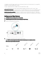
Page 29: ...7 7 Tighten the screws to secure the assembly to the wall 29 ...

Page 30: ... rail bracket includes the screws that are required for securing the bracket to the Edge Gateway 1 Align the screw holes on the DIN rail bracket with the screw holes at back of the Edge Gateway 2 Place the two M4x7 screws on the DIN rail bracket and secure it to the Edge Gateway 30 ...

Page 31: ...Secure the DIN rail mounting bracket to the Edge Gateway by using the two M4x7 screws provided NOTE Torque the screws at 8 0 5 kilograms centimeter 17 64 1 1 pounds inch on the DIN rail mounting bracket 31 ...

Page 32: ...IN rail at an angle and then pull the Edge Gateway down to compress the springs at the top of the DIN rail mounting bracket 5 Push the Edge Gateway towards the DIN rail bracket to secure the lower clip of the bracket onto the DIN rail 32 ...

Page 33: ...of the standard mount bracket and the DIN rail bracket NOTE The mounting brackets are shipped with only those screws that are required for securing the mounting brackets to the Edge Gateway Mounting dimensions Mounting instructions 1 Place the standard mount bracket on the wall and using the holes above the screw holes on the bracket mark the positions to drill the four holes 33 ...

Page 34: ...2 2 Drill four holes in the wall as marked 3 Insert and tighten four screws not supplied to the wall Purchase screws that fit the diameter of the screw holes 34 ...

Page 35: ...4 4 Align the screw holes on the standard mount bracket with the screws on the wall letting the bracket hang on the screws 35 ...

Page 36: ...5 5 Tighten the screws to secure the assembly to the wall 36 ...

Page 37: ...6 6 Align the screw holes on the DIN rail bracket with the screw holes at the back of the Edge Gateway 7 Place the two M4x7 screws on the DIN rail bracket and secure it to the Edge Gateway 37 ...

Page 38: ...8 8 Place the Edge Gateway on the standard mount at an angle and then pull the Edge Gateway down to compress the springs at the top of the DIN rail bracket 38 ...

Page 39: ...9 9 Push the Edge Gateway towards the DIN rail brackets to secure it on the standard mount bracket 39 ...

Page 40: ...il see Demounting DIN rail Mounting the Edge Gateway using the perpendicular mount NOTE The perpendicular mount is designed for DIN rail applications only 1 Align the screw holes on the perpendicular mount bracket with the screw holes on the Edge Gateway 40 ...

Page 41: ...2 2 Tighten the four M4x7 screws to secure the Edge Gateway to the perpendicular mount bracket NOTE Torque the screws at 8 0 5 kilograms centimeter 17 64 1 1 pounds inch 41 ...

Page 42: ...gn the screw holes on the DIN rail mount bracket with the screw holes on the perpendicular mount bracket and tighten the two screws NOTE Torque the screws at 8 0 5 kilograms centimeter 17 64 1 1 pounds inch 42 ...

Page 43: ...ay on the DIN rail at an angle and push the Edge Gateway down to compress the springs on the DIN rail mount brackets 5 Push the Edge Gateway towards the DIN rail brackets to secure the bottom of the bracket to the DIN rail 43 ...

Page 44: ...6 6 Push the Edge Gateway towards the DIN rail brackets to secure the lower clip of the bracket onto the DIN rail 7 Secure the Edge Gateway on the DIN rail 44 ...

Page 45: ...unt the Edge Gateway on the wall using the standard mount bracket or quick mount bracket 2 Place the cable control bar on the mounting bracket and secure it to the notch CAUTION Use the top cable control bar only with coaxial cable connections Do not use with antennas 45 ...

Page 46: ...cable control bar with the screw holes on the mounting bracket 4 Tighten the six M3 x 3 5 mm screws that secure the cable control bar to the mounting bracket NOTE Torque the screws at 5 0 5 kilograms centimeter 11 02 1 1 pounds inch 46 ...

Page 47: ...5 5 Connect the cables to the Edge Gateway 6 Loop the cable lock not supplied to secure each cable to the cable control bar 47 ...

Page 48: ... using a VESA mount The Edge Gateway can be mounted on a standard VESA mount 75 mm x 75 mm NOTE The VESA mount option is sold separately For VESA mounting instructions see the documentation that is shipped with the VESA mount 48 ...

Page 49: ...49 ...

Page 50: ...he Edge Gateway is installed inside the enclosure 1 Turn off your Edge Gateway 2 Connect the ZigBee dongle to any external USB port on your Edge Gateway 3 Turn on your Edge Gateway and complete the setup NOTE For more information about the ZigBee development see www silabs com 50 ...

Page 51: ... https support microsoft com en us Boot up and login Remote system configuration NOTE The Edge Gateway 3003 can also be configured remotely 1 Connect a network cable from the Ethernet port one on the Edge Gateway to a DHCP enabled network or router that provides IP addresses NOTE The first time boot to Windows takes about five minutes for system configuration Subsequent boots take approximately 50...

Page 52: ...e from www dell com support Dell OS Recovery Tool Download and install the Dell OS Recovery Tool on your computer A blank USB flash drive with at least 8 GB of storage space NET Framework 4 5 2 or higher A working computer with administrator user rights and at least 8 GB of available data storage to download the Dell ISO recovery image 1 Double click the Dell OS Recovery Tool icon from your deskto...

Page 53: ...ces see technet microsoft com en us library cc749022 v ws 10 aspx System Shutdown and Restart Click Start and then press Power then Restart or Shutdown the Edge Gateway LAN WLAN Network configuration Click Start and then type 6HWWLQJV and open the Settings window Select Network Internet from the settings menu Bluetooth configuration Click Start and then type 6HWWLQJV and open the Settings window S...

Page 54: ...system automatically and restarts multiple times to apply all the configurations The system takes approximately one minute to boot to the operating system When prompted log in using the default credentials The default user name and password is DGPLQ both lowercase and the default computer name is the service tag For example 8EXQWX RUH RQ WW ORFDOKRVW ORJLQ DGPLQ 3DVVZRUG Updating operating system ...

Page 55: ...he factory the OS is usually set to UTC time zone To change the time zone to your location you will must run the command DGPLQ ORFDOKRVW a VXGR WLPHGDWHFWO KHOS WKH KHOS ILOH DERYH ZLOO WHOO RX FRPPDQGV RX QHHG WR NQRZ System reboot Run the following command DGPLQ ORFDOKRVW VXGR UHERRW Returns 6 VWHP UHERRW VXFFHVVIXOO Root user credential Run the following command DGPLQ ORFDOKRVW VXGR VX Returns ...

Page 56: ...nline BIOS firmware update 1 Ensure that the path to LVFS server is correct YDU VQDS XHIL IZ WRROV HWF IZXSG FRQI 2 Set the URL to the following location KWWSV VHFXUH OYIV UKFORXG FRP GRZQORDGV ILUPZDUH F D F I E E H D D PO J 3 Check current firmware details VXGR XHIL IZ WRROV IZXSGPJU JHW GHYLFHV 4 Check if the update is available from LVFS service VXGR XHIL IZ WRROV IZXSGPJU UHIUHVK 5 Download t...

Page 57: ...HQ 5 E WHV 7 E WHV OR LQN HQFDS RFDO RRSEDFN LQHW DGGU 0DVN LQHW DGGU 6FRSH RVW 83 223 5811 1 078 0HWULF 5 SDFNHWV HUURUV GURSSHG RYHUUXQV IUDPH 7 SDFNHWV HUURUV GURSSHG RYHUUXQV FDUULHU ROOLVLRQV W TXHXHOHQ 5 E WHV 7 E WHV DGPLQ ORFDOKRVW a WLAN wlan0 Use these identifiers in the following examples VVLGQDPH LRWLVYODE where VVLG is the name of access point QDPH WHVWZLIL where QDPH is the connectio...

Page 58: ...DJHU QPFOL FRQ PRGLI WHVWZLIL ZLIL VHF SVN KDSS Enter the following at the command prompt to bring up the connection allows it to connect to the access point and get an IP address QHWZRUN PDQDJHU QPFOL FRQ XS LG QDPH For example QHWZRUN PDQDJHU QPFOL FRQ XS LG WHVWZLIL B Bluetooth Run the following commands For example bluetooth keyboard 1 Start the bluetoothctl console EOXH EOXHWRRWKFWO D 2 Turn ...

Page 59: ...s security whitepaper TPM is supported only on devices that have TPM hardware and for those products which offers Snappy enhanced security support The TPM on off setting is configurable in the firmware and manageable in the operating system Running command DGPLQ ORFDOKRVW OV GHY WSP If TPM is turned off the device node GHY WSP does not exist SODQR XEXQWX ORFDOKRVW OV GHY WSP V FDQQRW DFFHVV GHY WS...

Page 60: ...dware USB keyboard USB mouse Ubuntu workstation with Ubuntu 14 04 or higher Flashing new Ubuntu OS image 1 Insert a USB flash drive into the Ubuntu Desktop workstation 2 Download FDUDFDOOD DOSKD LPJ to Downloads directory 3 Flash the installation image to USB flash drive a Start the Terminal application It can be found by typing 7HUPLQDO in the Unity Dash CAUTION The GG command erases the content ...

Page 61: ...16 On the connected computer running Ubuntu Core access Dell Command Configure using the command GFF FFWN For more information on how to use the Dell Command Configure application see the Dell Command Configure Installation Guide and User s Guide at www dell com dellclientcommandsuitemanuals For more information about BIOS settings on the Edge Gateway see Default BIOS settings Flashing BIOS You mu...

Page 62: ... 16 Update the BIOS using the following methods UEFI capsule update Dell Command Configure DCC Edge Device Manager EDM UEFI capsule update The fwupgmgr tool or commands are used to update UEFI BIOS firmware on the system For more information about UEFI capsule update methods see UEFI capsule update capability Dell Command Configure DCC Use DCC to update and configure the BIOS settings For more inf...

Page 63: ...Edge Gateway Service Manual Dell SupportAssist For Dell OpenManage Essentials Quick Start Guide Dell Command Configure User s Guide Dell Command Configure Reference Guide Dell Command Monitor User s Guide Dell Command PowerShell Provider User s Guide For more information on using Dell Data Protection Encryption see the documentation for the software at www dell com support manuals 63 ...

Page 64: ...oved by Dell is the sole responsibility of the user or configurator or operator to reassess the equipment in accordance to all applicable international Safety EMC and RF standards The Dell authorized antenna specifications are as follows Mobile Broadband Main Dipole LTE Auxiliary PIFA GPS WiFi Zigbee Monopole The following tables provide the gain specifications for different antenna positions Tabl...

Page 65: ...9 2 5 1710 1880 2 3 2 0 1850 1990 3 6 3 2 1920 2170 3 6 3 2 Table 14 WiFi GPS antenna maximum gain dBi Antenna position Bent Antenna position Straight Frequency MHz GPS dBi WLAN dBi GPS dBi WLAN dBi 1561 1602 2 6 2 4 2400 2500 3 4 1 6 De mounting from DIN rail bracket 1 Pull the Edge Gateway down to release from DIN rail bracket 2 Lift the Edge Gateway bracket off the DIN rail 65 ...

Page 66: ...isable Enabled Audio Enable Audio Enable Disable Enabled Miscellaneous Devices Enable WWAN Enable Disable Enabled Enable WLAN Bluetooth Enable Disable Enabled Enable CANBus Enable Disable Enabled Enable ZigBee Enable Disable Enabled Enable Dedicated GPS Radio Enable Disable Enabled Enable MEMs Sensor Enable Disable Enabled Watchdog Timer Support Watchdog Timer Support Enable Watchdog Timer Enable ...

Page 67: ...mware Updates UEFI Capsule Firmware Updates Enable UEFI Capsule Firmware Updates Enable Disable Enabled TPM 2 0 Security TPM 2 0 Security TPM 2 0 Security Enable Disable Enabled TPM On Enable Disable Enabled PPI Bypass for Enable Commands Enable Disable Disabled PPI Bypass for Disable Commands Enable Disable Disabled Attestation Enable Enable Disable Enabled Key Storage Enable Enable Disable Enabl...

Page 68: ...lue Enable CPUID Limit Enable Disable Disabled Power management BIOS level 1 BIOS level 2 BIOS level 3 Item Default value Auto On Time Auto On Time Time Selection HH MM A P Auto On Time if Wake Period 0 12 00AM Value Selection 0 254 Auto Wake Period 0 254 minutes 000 Day Selection Disabled Every Day Weekdays Select Days Disabled Under Select Days when enabled Sunday Monday Saturday Not applicable ...

Page 69: ...ation Technology Enable Disable Enabled Maintenance BIOS level 1 BIOS level 2 BIOS level 3 Item Default value Service Tag Service Tag System Service Tag text entry capability when blank Not applicable Asset Tag Asset Tag System Asset Tag text entry capability Not applicable SERR Messages SERR Messages Enable SERR Messages Enable Disable Enabled BIOS Downgrade BIOS Downgrade Allow BIOS Downgrade En...

Page 70: ...or support link based on your requirement or choose the method of contacting Dell that is convenient for you Dell provides several online and telephone based support and service options Availability varies by country and product and some services may not be available in your area NOTE If you do not have an active internet connection you can find the contact information on your purchase invoice pac...

Reviews: