background image


Service Manual–E2723HN


Regulatory model: E2723HNc 


Version: 02 

Date:2021/10/11

Summary of Contents for E Series

Page 1: ...1 Service Manual E2723HN Regulatory model E2723HNc Version 02 Date 2021 10 11 ...

Page 2: ...ETY General Power Safety 5 2 Exploded view diagram with list of items 6 3 Wiring connectivity diagram 8 4 How to connect and disconnect power cable connectivity cable 9 5 Disassembly and Assembly Procedures 11 5 1 Disassembly SOP 11 5 2 Assembly SOP 15 6 Trouble shooting instructions ...

Page 3: ...erenced in your computer documentation before placing a monitor or other devices on top of your computer Ensure that nothing rests on your equipment s cables and that the cables are not located where they can be stepped on or tripped over Ensure that all cables are connected to the appropriate connectors Some connectors have a similar appearance and may be easily confused for example do not plug a...

Page 4: ...nd then discharge into another object such as your computer To prevent ESD damage you should discharge static electricity from your body before you interact with any of your equipment s internal electronic components such as a memory module You can protect against ESD by touching a metal grounded object such as an unpainted metal surface on your computer s I O panel before you interact with anythi...

Page 5: ...as risk of electric shock and or fire Ensure that the ground prong of the power plug is inserted into the mating ground contact of the power strip Be sure to grasp the plug not the cable when disconnecting equipment from an electric socket If your equipment uses an AC adapter Use only the Dell provided AC adapter approved for use with this device Use of another AC adapter may cause a fire or explo...

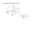
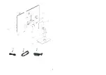
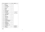
Page 6: ...6 2 Exploded view diagram with list of items ...

Page 7: ...7 21 22 23 ...

Page 8: ...OARD 1 11 MAIN BOARD 1 12 MAINFRAME 1 13 STAND BUTTON 1 14 VESA RRACKET 2 15 REAR COVER 1 16 PLATE 1 17 DELL LOGO 1 18 COVER VESA 1 19 HINGE ASS Y 1 20 BASE ASS Y 1 S1 SCREW KEY 3 S2 SCREW POWERBOARD 2 S3 SCREW MAINBOARD 2 S4 SCREW AC 1 S5 SCREW PANEL 2 S6 SCREW BUTTON 1 S7 SCREW VESA 4 S8 SCREW REAR COVER 2 21 Power Cable 1 See NOTE 22 HDMI 1 4 1 See NOTE 23 VGA CABLE 1 See NOTE ...

Page 9: ...www dell com support 2 Verify your country or region in the Choose A Country Region drop down menu at the bottom right corner of the page 3 Click Contact Us next to the country dropdown 4 Select the appropriate service or support link based on your need 5 Choose the method of contacting Dell that is convenient for you ...

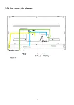
Page 10: ...10 3 Wiring connectivity diagram ...

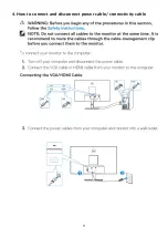
Page 11: ...11 4 How to connect and disconnect power cable connectivity cable ...

Page 12: ...ll will deem warranty void if any disassembly is done on the monitors Tools Required List the type and size of the tools that would typically can be used to disassemble the product to a point where components and materials requiring selective treatment can be removed Tool Description Screwdriver Phillip head Hexagonal head Penknife ...

Page 13: ...13 5 1Disassembly Procedures Step Figure Remark Remove Stand ass y Pull up the stand ass y Remove the rear cover Remove the 6 pcs screws ...

Page 14: ...o insert from the bottom site and then open the rear cover Remove the mainframe Remove the tapes Disconnect the cables and remove the 2 pcs screws on the site of the mainframe and 2 pcs of hexagon screws Remove maylar ...

Page 15: ...15 Remove the powerbard and mainboard Remove the screws on the mainboard and power board Mainboard and powerboard ...

Page 16: ...semble the powerbard and mainboard Tighten the screws on the boards Assemble maylar connect the cables and tighten the 2 pcs screws on the site of the mainframe and 2 pcs of hexagon screws assemble the mainframe Re stick the tapes ...

Page 17: ...17 Assemble the rear cover tighten the 6 pcs screws Assemble the stand ass y Pull in the stand ass y ...

Page 18: ...18 6 Trouble shooting instructions ...

Page 19: ...19 ...

Page 20: ...20 ...

Page 21: ...21 ...

Page 22: ...22 ...

Page 23: ...23 ...

Page 24: ...24 ...

Page 25: ...25 ...

Reviews: