Dell D2215H, User Manual
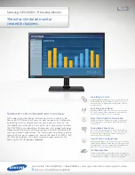
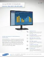
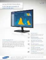
The Dell D2215H User Manual is an essential resource for optimizing your experience with this high-performance monitor. Download the comprehensive manual for free from our website, ensuring that you have all the necessary information at your fingertips. Explore the D2215H's features and functionality to maximize your productivity and enjoyment.
Share
Download


Reviews:
No comments