background image

w w w . d e l l . c o m   |   s u p p o r t . d e l l . c o m

Dell™ Dimension™ 9200

Owner’s Manual

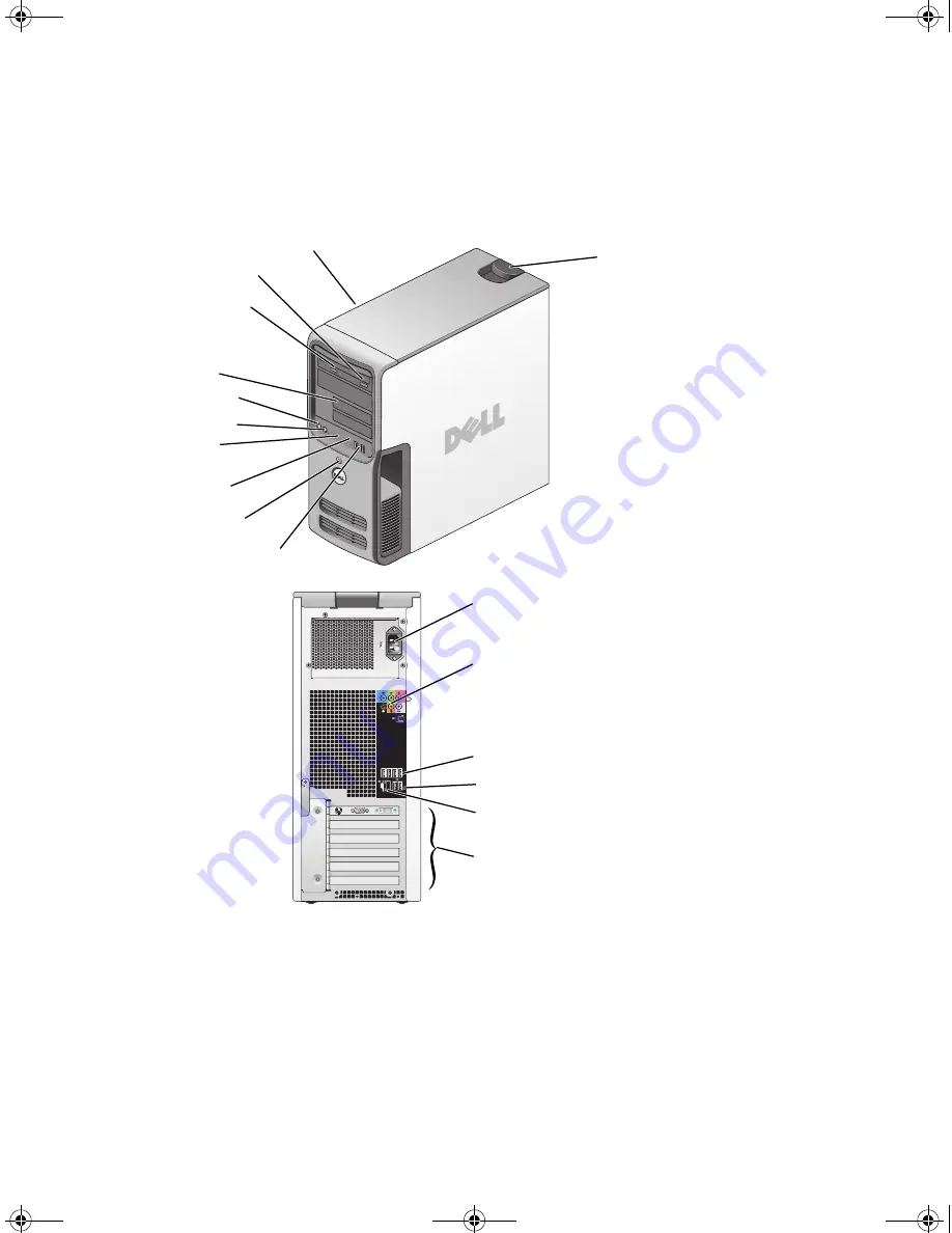
FlexBays (2) for optional
floppy drive or optional 
Media Card Reader

hard drive activity light

power button

microphone connector

 headphone connector

CD or DVD activity light

CD or DVD eject button

diagnostic lights

USB 2.0 connectors (2)

cover release latch

Service Tag

power connector

USB 2.0 connectors (4) (rear quad)

network adapter

audio connectors

card slots for PCI Express x1 (1),
PCI Express x16 (1), PCI Express x4 (1), 
PCI (3)

USB 2.0 connectors (2) (rear dual)

Model DCTA

DIM_book.book  Page 1  Monday, October 15, 2007  11:04 AM

Summary of Contents for 9200

Page 1: ...ne connector headphone connector CD or DVD activity light CD or DVD eject button diagnostic lights USB 2 0 connectors 2 cover release latch Service Tag power connector USB 2 0 connectors 4 rear quad network adapter audio connectors card slots for PCI Express x1 1 PCI Express x16 1 PCI Express x4 1 PCI 3 USB 2 0 connectors 2 rear dual Model DCTA DIM_book book Page 1 Monday October 15 2007 11 04 AM ...

Page 2: ...go Inspiron DellPrecision Dimension OptiPlex Latitude PowerEdge PowerVault PowerApp PowerConnect XPS DellNet Dell TravelLite Dell OpenManage and StrikeZone are trademarks of Dell Inc Core is trademark of Intel Corporation Intel Pentium Intel SpeedStep Celeron and Viiv are registered trademarks of Intel Corporation Microsoft Windows and Outlook are registered trademarks of Microsoft Corporation in ...

Page 3: ...ing Up a Printer 20 Printer Cable 20 Connecting a USB Printer 20 Connecting to the Internet 21 Setting Up Your Internet Connection 21 Setting Up a Home and Office Network 22 Connecting to a Network Adapter 22 Network Setup Wizard 23 Transferring Information to a New Computer 23 Running the Files and Settings Transfer Wizard With the Operating System CD 24 Running the Files and Settings Transfer Wi...

Page 4: ...the Floppy Drive 35 Cleaning CDs and DVDs 35 2 Optimizing Performance 37 Hyper Threading 37 About Your RAID Configuration 37 RAID Level 0 Configuration 38 RAID Level 1 Configuration 38 Configuring Your Computer for RAID 39 Using the Intel RAID Option ROM Utility 40 Using the Intel Application Accelerator 42 Dell DataSafe Optional 46 Intel Viiv Technology Optional 46 Using Intel Viiv Quick Resume T...

Page 5: ...s responding 55 A program stops responding 55 A program crashes repeatedly 55 A program is designed for an earlier Windows operating system 56 A solid blue screen appears 56 Other software problems 56 Memory Problems 57 Mouse Problems 57 Network Problems 58 Power Problems 59 Printer Problems 60 Scanner Problems 60 Sound and Speaker Problems 61 No sound from speakers 61 No sound from headphones 62 ...

Page 6: ...ec 74 5 Removing and Installing Parts 77 Before You Begin 77 Recommended Tools 77 Turning Off Your Computer 77 Before Working Inside Your Computer 78 Removing the Computer Cover 78 Inside View of Your Computer 80 System Board Components 81 Memory 82 Memory Overview 82 Installing Memory 83 Removing Memory 85 Cards 86 PCI Cards 86 PCI Express Cards 91 Drive Panels 100 Removing the Drive Panel 100 Re...

Page 7: ...e 116 Removing a CD DVD Drive 117 Installing a CD DVD Drive 118 Battery 120 Replacing the Battery 120 Replacing the Computer Cover 121 6 Appendix 123 Specifications 123 System Setup 127 Overview 127 Entering System Setup 127 System Setup Options 129 Boot Sequence 132 Clearing Forgotten Passwords 134 Clearing CMOS Settings 135 Dell Technical Support Policy U S Only 135 Definition of Dell Installed ...

Page 8: ...8 Contents FCC Notice U S Only 136 FCC Class B 136 Contacting Dell 137 Glossary 159 Index 171 DIM_book book Page 8 Monday October 15 2007 11 04 AM ...

Page 9: ...onal and may not ship with your computer Documentation and drivers are already installed on your computer You can use the CD to reinstall drivers see Drivers on page 70 run the Dell diagnostics see Dell Diagnostics on page 68 or access your documentation Readme files may be included on your CD to provide last minute updates about technical changes to your computer or advanced technical reference m...

Page 10: ...ations and white papers Downloads Certified drivers patches and software updates Desktop System Software DSS If you reinstall the operating system for your computer you should also reinstall the DSS utility DSS automatically detects your computer and operating system and installs the updates appropriate for your configuration providing critical updates for your operating system and support for Del...

Page 11: ...ter To reinstall your operating system see Restoring Your Operating System on page 72 After you reinstall your operating system use the Drivers and Utilities CD to reinstall drivers for the devices that came with your computer Your operating system product key label is located on your computer NOTE The color of your CD varies according to the operating system you ordered How to use Linux E mail di...

Page 12: ...12 Finding Information DIM_book book Page 12 Monday October 15 2007 11 04 AM ...

Page 13: ...Setting Up and Using Your Computer 13 Setting Up and Using Your Computer Front View of the Computer 2 3 9 4 8 10 7 5 6 1 11 12 DIM_book book Page 13 Monday October 15 2007 11 04 AM ...

Page 14: ...s cameras or bootable USB devices For more information on booting to a USB device see System Setup Options on page 129 NOTE It is recommended that you use the back USB connectors for devices that typically remain connected such as printers and keyboards 7 power button Press the power button to turn on the computer NOTICE To avoid losing data do not use the power button to turn off the computer Ins...

Page 15: ... Plug USB network S PDIF and audio devices into the appropriate connectors see Back Panel Connectors on page 16 3 card slots 6 Access connectors for any installed PCI or PCI Express cards 4 power selection switch Manually select AC input power 115 volts or 230 volts 2 1 3 4 DIM_book book Page 15 Monday October 15 2007 11 04 AM ...

Page 16: ...etwork cable has been securely attached On computers with an additional network connector card use the connectors on the card and on the back of the computer when setting up multiple network connections such as a separate intra and extranet NOTE It is recommended that you use Category 5 wiring and connectors for your network If you must use Category 3 wiring force the network speed to 10 Mbps to e...

Page 17: ...hone connector Use the green line out connector to attach headphones and most speakers with integrated amplifiers On computers with a sound card use the connector on the card 9 microphone connector Use the pink microphone connector to attach a personal computer microphone for voice or musical input into a sound or telephony program On computers with a sound card use the connector on the card 10 ce...

Page 18: ...er 3 Connect the other monitor to the optional DVI to VGA adapter then connect the adapter to the white DVI connector on the back of the computer Connecting One Monitor With a VGA connector and One Monitor With a DVI Connector 1 Follow the procedures in Before You Begin on page 77 2 Connect the VGA connector of the first monitor to the blue VGA connector on the back of the computer 3 Connect the D...

Page 19: ...The Microsoft Windows desktop displays on the primary monitor 2 Enable clone mode or extended desktop mode in the display settings In clone mode both monitors display the same image In extended desktop mode you can drag objects from one screen to the other effectively doubling the amount of viewable work space For information on changing the display settings for your graphics card see the user s g...

Page 20: ...e in the computer box Connecting a USB Printer NOTE You can connect USB devices while the computer is turned on 1 Complete the operating system setup if you have not already done so 2 Install the printer driver if necessary see the documentation that came with your printer 3 Attach the USB printer cable to the appropriate USB connector on the computer and the printer The connectors fit only one wa...

Page 21: ...neously Cable modem connections that provide high speed Internet access through your local cable TV line NOTE If you use a dial up connection you need an add in PCI modem expansion card If you are using a dial up connection connect a telephone line to the modem connector on your computer and to the telephone wall jack before you set up your Internet connection If you are using a DSL or cable modem...

Page 22: ...n the screen to complete the setup 6 Click the appropriate option under How do you want to connect to the Internet and then click Next 7 Use the setup information provided by your ISP to complete the setup If you are having problems connecting to the Internet see E Mail Modem and Internet Problems on page 51 If you cannot connect to the Internet but have successfully connected in the past the ISP ...

Page 23: ...is computer connects directly to the Internet enables the integrated firewall provided with Windows XP Service Pack 4 Complete the checklist and required preparations 5 Return to the Network Setup Wizard and follow the instructions on the screen Transferring Information to a New Computer The Microsoft Windows XP operating system provides a Files and Settings Transfer Wizard to move data from a sou...

Page 24: ...les and Settings Transfer Wizard You can use the optional Operating System CD for this process or you can create a wizard disk with the Files and Settings Transfer Wizard Running the Files and Settings Transfer Wizard With the Operating System CD NOTE This procedure requires the Operating System CD This CD is optional and may not be included with all computers To prepare the new computer for the f...

Page 25: ...ble media To create a wizard disk use your new computer with Windows XP and perform the following steps 1 Click the Start button 2 Click Files and Settings Transfer Wizard 3 When the Files and Settings Transfer Wizard welcome screen appears click Next 4 On the Which computer is this screen click New Computer then click Next 5 On the Do you have a Windows XP CD screen click I want to create a Wizar...

Page 26: ...of the settings and files have been applied the Finished screen appears 3 Click Finished and then restart the new computer NOTE For more information about this procedure search support dell com for document PA1089586 How Do I Transfer Files From My Old Computer to My New Dell Computer Using the Microsoft Windows XP Operating System NOTE Access to the Dell Knowledge Base document may not be availab...

Page 27: ...E Ensure that you observe all copyright laws when you create CDs or DVDs A CD player includes the following basic buttons A DVD player includes the following basic buttons Play Move backward within the current track Pause Move forward within the current track Stop Go to the previous track Eject Go to the next track Stop Restart the current chapter Play Fast forward DIM_book book Page 27 Monday Oct...

Page 28: ...g DVD playback adjust the display properties 1 Click the Start button and then click Control Panel 2 Under Pick a category click Appearance and Themes 3 Under Pick a task click Change the screen resolution 4 In the Display Properties window click and drag the bar in Screen resolution to change the setting to 800 by 600 pixels 5 Under Color quality click the drop down menu and then click Medium 16 ...

Page 29: ...lick the Disc Copy button The computer reads your source CD or DVD and copies the data to a temporary folder on your computer hard drive When prompted insert a blank CD or DVD into the drive and click OK If you have two CD DVD drives select the drive into which you have inserted your source CD or DVD and click the Disc Copy button The computer copies the data from the source CD or DVD to the blank...

Page 30: ...on provided with your DVD player or contact the manufacturer Do not burn a blank CD R or CD RW to its maximum capacity for example do not copy a 650 MB file to a blank 650 MB CD The CD RW drive needs 1 2 MB of blank space to finalize the recording Use a blank CD RW to practice CD recording until you are familiar with CD recording techniques If you make a mistake you can erase the data on the CD RW...

Page 31: ...pactFlash Type I and II CF I II MicroDrive Card SecureDigital Card SD MultiMediaCard MMC Memory Stick MS MS Pro For information on installing a Media Card Reader see Installing a Media Card Reader on page 115 1 xD Picture Card and SmartMedia SMC 2 Memory Stick MS MS Pro 3 SecureDigital Card SD and MultiMediaCard MMC 4 CompactFlash Type I and II CF I II and MicroDrive Card 1 2 3 4 DIM_book book Pag...

Page 32: ...tandby mode or hibernate mode to reduce power to the entire computer When the computer exits from a power conservation mode it returns to the operating state it was in prior to entering the mode NOTE Windows XP Professional includes security and networking features not available in Windows XP Home Edition When a Windows XP Professional computer is connected to a network different options related t...

Page 33: ...puter to you If the computer s hard drive becomes corrupted Windows XP recreates the hibernate file automatically Power Options Properties Define your standby mode settings hibernate mode settings and other power settings in the Power Options Properties window To access the Power Options Properties window 1 Click the Start button then click Control Panel 2 Define your power settings on the Power S...

Page 34: ...ram these functions click an option from the corresponding drop down menu and click OK Hibernate Tab The Hibernate tab allows you to enable hibernate mode If you want to use the hibernate settings as defined on the Power Schemes tab click the Enable hibernate support check box on the Hibernate tab For more information on power management options 1 Click the Start button then click Help and Support...

Page 35: ... ball and retainer ring and then turn the retainer ring clockwise until it clicks into place Cleaning the Floppy Drive NOTICE Do not attempt to clean drive heads with a swab You might accidentally misalign the heads which prevents the drive from operating Clean your floppy drive using a commercially available cleaning kit These kits contain pretreated floppies to remove contaminants that accumulat...

Page 36: ...36 Setting Up and Using Your Computer DIM_book book Page 36 Monday October 15 2007 11 04 AM ...

Page 37: ...nabled the processor is listed twice You can enable or disable Hyper Threading through system setup For more information on accessing system setup see Entering System Setup on page 127 For more information on Hyper Threading search the Knowledge Base on the Dell Support website at support dell com About Your RAID Configuration This section provides an overview of the RAID configuration you may hav...

Page 38: ...other advantage of a RAID level 0 configuration is that it utilizes the full storage capacities of the drives For example two 120 GB drives combine to provide 240 GB of hard drive space on which to store data NOTE In a RAID level 0 configuration the size of the configuration is equal to the size of the smallest drive multiplied by the number of drives in the configuration RAID Level 1 Configuratio...

Page 39: ...he first method uses the Intel RAID Option ROM utility and is performed before you install the operating system onto the hard drive The second method uses the Intel Matrix Storage Manager or Intel Matrix Storage Console and is performed after you have installed the operating system and the Intel Matrix Storage Console Both methods require that you set your computer to RAID enabled mode before begi...

Page 40: ...de on page 39 2 Press Ctrl i when you are prompted to enter the Intel RAID Option ROM utility 3 Press the up and down arrow keys to highlight Create RAID Volume then press Enter 4 Enter a RAID volume name or accept the default name then press Enter 5 Press the up and down arrow keys to select RAID0 Stripe then press Enter 6 If there are more than two hard drives available press the up and down arr...

Page 41: ...AID volume 10 Confirm that the correct volume configuration is displayed on the main Intel RAID Option ROM utility screen 11 Use the up and down arrow keys to select Exit and then press Enter 12 Install the operating system see Using Microsoft Windows XP System Restore on page 72 Deleting a RAID Volume NOTICE The following procedure will result in the loss of all data on the hard drives in your RA...

Page 42: ...hard drives in your RAID configuration Back up any data you want to keep before continuing 1 Set your computer to RAID enabled mode see Setting Your Computer to RAID Enabled Mode on page 39 2 Click Start and point to Programs Intel Application Accelerator Intel Matrix Storage Manager to launch the Intel Storage Utility NOTE If you do not see an Actions menu option you have not yet set your compute...

Page 43: ...k the right arrow Click to add a second hard drive until two drives appear in the Selected window and then click Next 7 In the Specify Volume Size window select the Volume Size desired then click Next 8 Click Finish to create the volume or click Back to make changes 9 Follow Microsoft Windows procedures for creating a partition on the new RAID volume Deleting a RAID Volume NOTE While this procedur...

Page 44: ...which you want to migrate and click Next NOTE The source hard drive should be the hard drive containing the data or operating system files that you want to keep on the RAID volume 9 On the Select Member Hard Drive screen double click the hard drive s to select the member drive s to span the stripe array then click Next 10 On the Specify Volume Size screen select the Volume Size you want then click...

Page 45: ...r or the Intel RAID Option ROM utility When a member of the RAID level 1 configuration fails the computer automatically rebuilds the mirror configuration using the spare hard drive as the failed member s replacement To mark a drive as a spare hard drive 1 Click the Start button and point to Programs Intel Application Accelerator Intel Matrix Storage Manager to launch the Intel Storage Utility 2 Ri...

Page 46: ...ard drive failure Intel Viiv Technology Optional Intel Viiv technology is a technology aimed at the digital home enthusiast that includes A BIOS that supports Intel Quick Resume Technology Device drivers This technology allows the user s system to quickly return to an active state after non use Intel Viiv technology is an option for systems that are ordered with Microsoft Windows XP Media Center E...

Page 47: ...d down arrow keys to highlight the Quick Resume option then press Enter to access the menu 4 Press the left and right arrow keys to highlight the On option and then press Enter to enable the Quick Resume feature Enabling the QRT Feature in the Operating system 1 Click the Start button then click Control Panel 2 Click the Away tab 3 Ensure that the check boxes for Enable away mode and Options are c...

Page 48: ...48 Optimizing Performance DIM_book book Page 48 Monday October 15 2007 11 04 AM ...

Page 49: ...gs restore your previous SATA operation settings and retry booting to the operating system Battery Problems CAUTION There is a danger of a new battery exploding if it is incorrectly installed Replace the battery only with the same or equivalent type recommended by the manufacturer Discard used batteries according to the manufacturer s instructions CAUTION Before you perform any of the procedures i...

Page 50: ...ruses Viruses can sometimes prevent Windows from recognizing the drive TEST THE DRIVE Insert another floppy CD or DVD to eliminate the possibility that the original is defective Insert a bootable floppy and restart the computer CLEAN THE DRIVE OR DISK See Cleaning Your Computer on page 34 CHECK THE CABLE CONNECTIONS RUN THE HARDWARE TROUBLESHOOTER See Using Microsoft Windows XP System Restore on p...

Page 51: ...ed an error occurs Try closing all programs before you write to the CD DVD RW TURN OFF STANDBY MODE IN WINDOWS BEFORE WRITING TO A CD DVD RW DISC Search for the keyword standby in Windows Help RUN CHECK DISK 1 Click Start then click My Computer 2 Right click Local Disk C 3 Click Properties 4 Click the Tools tab 5 Under Error checking click Check Now 6 Click Scan for and attempt recovery of bad sec...

Page 52: ...UN THE MODEM HELPER DIAGNOSTICS Click Start point to All Programs and then click Modem Helper Follow the instructions on the screen to identify and resolve modem problems Modem Helper is not available on all computers VERIFY THAT THE MODEM IS COMMUNICATING WITH WINDOWS 1 Click Start then click Control Panel 2 Click Printers and Other Hardware 3 Click Phone and Modem Options 4 Click the Modems tab ...

Page 53: ...or installation instructions ALERT AIR TEMPERATURE SENSOR NOT DETECTED The ambient thermal sensor is not detected Press F1 to continue or F2 to enter system setup drive letter IS NOT ACCESSIBLE THE DEVICE IS NOT READY The drive cannot read the disk Insert a disk into the drive and try again INSERT BOOTABLE MEDIA Insert a bootable floppy or CD NON SYSTEM DISK ERROR Remove the floppy from the drive ...

Page 54: ...E The Media Card Reader appears as a mapped drive only when it is connected Each of the four Media Card Reader slots are mapped to a drive even if no media is installed If you attempt to access the Media Card Reader when no media is inserted you are prompted to insert media FLEXBAY DEVICE IS DISABLED There is a FlexBay disable option in the BIOS setup that appears only when the FlexBay device is i...

Page 55: ...ng Software and Hardware Incompatibilities on page 72 CHECK THE DIAGNOSTIC LIGHTS See Diagnostic Lights on page 65 ENSURE THAT THE POWER CABLE IS FIRMLY CONNECTED TO THE COMPUTER AND TO THE ELECTRICAL OUTLET TURN THE COMPUTER OFF If you are unable to get a response by pressing a key on your keyboard or moving your mouse press and hold the power button for at least 8 to 10 seconds until the compute...

Page 56: ...t 8 to 10 seconds until the computer turns off and then restart your computer CHECK THE SOFTWARE DOCUMENTATION OR CONTACT THE SOFTWARE MANUFACTURER FOR TROUBLESHOOTING INFORMATION Ensure that the program is compatible with the operating system installed on your computer Ensure that your computer meets the minimum hardware requirements needed to run the software See the software documentation for i...

Page 57: ...cating with the memory Run the Dell Diagnostics see Dell Diagnostics on page 68 IF YOU EXPERIENCE OTHER MEMORY PROBLEMS Reseat the memory modules see Memory on page 82 to ensure that your computer is successfully communicating with the memory Ensure that you are following the memory installation guidelines see Installing Memory on page 83 Your computer supports DDR2 memory For more information abo...

Page 58: ...Click Mouse 3 Adjust the settings as needed REINSTALL THE MOUSE DRIVER See Reinstalling Drivers on page 71 RUN THE HARDWARE TROUBLESHOOTER See Resolving Software and Hardware Incompatibilities on page 72 CHECK THE NETWORK CABLE CONNECTOR Ensure that the network cable is firmly inserted into the network connector on the back of the computer and the network jack CHECK THE NETWORK LIGHTS ON THE BACK ...

Page 59: ... to verify that the computer turns on properly Ensure that the electrical outlet is working by testing it with another device such as a lamp Ensure that the main power cable and front panel cable are securely connected to the system board see System Board Components on page 81 IF THE POWER LIGHT IS STEADY AMBER A device may be malfunctioning or incorrectly installed Remove and then reinstall the m...

Page 60: ... printer documentation for cable connection information Ensure that the printer cables are securely connected to the printer and the computer see Setting Up a Printer on page 20 TEST THE ELECTRICAL OUTLET Ensure that the electrical outlet is working by testing it with another device such as a lamp VERIFY THAT THE PRINTER IS RECOGNIZED BY WINDOWS 1 Click Start click Control Panel and then click Pri...

Page 61: ...ANNER IS RECOGNIZED BY MICROSOFT WINDOWS 1 Click Start click Control Panel and then click Printers and Other Hardware 2 Click Scanners and Cameras If your scanner is listed Windows recognizes the scanner REINSTALL THE SCANNER DRIVER See the scanner documentation for instructions CHECK THE SPEAKER CABLE CONNECTIONS Ensure that the speakers are connected as shown on the setup diagram supplied with t...

Page 62: ...ee Reinstalling Drivers on page 71 RUN THE HARDWARE TROUBLESHOOTER See Resolving Software and Hardware Incompatibilities on page 72 CHECK THE HEADPHONE CABLE CONNECTION Ensure that the headphone cable is securely inserted into the headphone connector see Front View of the Computer on page 13 ADJUST THE WINDOWS VOLUME CONTROL Click or double click the speaker icon in the lower right corner of your ...

Page 63: ...the contrast and brightness demagnetizing degaussing the monitor and running the monitor self test MOVE THE SUBWOOFER AWAY FROM THE MONITOR If your speaker system includes a subwoofer ensure that the subwoofer is at least 60 cm 2 ft away from the monitor MOVE THE MONITOR AWAY FROM EXTERNAL POWER SOURCES Fans fluorescent lights halogen lamps and other electrical devices can cause the screen image t...

Page 64: ...64 Solving Problems DIM_book book Page 64 Monday October 15 2007 11 04 AM ...

Page 65: ... malfunctions the sequence of the lights help to identify the problem Light Pattern Problem Description Suggested Resolution The computer is in a normal off condition or a possible pre BIOS failure has occurred All four diagnostic lights display solid green and then turn off after the system successfully boots to the operating system Plug the computer into a working electrical outlet see Power Pro...

Page 66: ...emory of the same type into your computer see Installing Memory on page 83 If the problem persists contact Dell see Contacting Dell on page 137 A possible graphics card failure has occurred Reseat any installed graphics card see Cards on page 86 If available install a working graphics card into your computer If the problem persists contact Dell see Contacting Dell on page 137 A possible floppy dri...

Page 67: ...ts for memory module connector placement exist see Memory on page 82 Ensure that the memory you are using is supported by your computer see Memory on page 123 If the problem persists contact Dell see Contacting Dell on page 137 A possible expansion card failure has occurred 1 Determine if a conflict exists by removing a card not a graphics card and restarting the computer see Cards on page 86 2 If...

Page 68: ...ting in quick resume mode See Using Intel Viiv Quick Resume Technology QRT on page 46 for additional information Press the power button Move the mouse Press any key on the keyboard Press any key on the optional MCE remote control If the problem persists contact Dell see Contacting Dell on page 137 Another failure has occurred Ensure that all hard drive and CD DVD cables are properly connected to t...

Page 69: ... for more information Option Function Express Test Performs a quick test of devices This test typically takes 10 to 20 minutes and requires no interaction on your part Run Express Test first to increase the possibility of tracing the problem quickly Extended Test Performs a thorough check of devices This test typically takes 1 hour or more and requires you to answer questions periodically Custom T...

Page 70: ...e your operating system Reinstall your operating system Connect or install a new device Identifying Drivers If you experience a problem with any device identify whether the driver is the source of your problem and if necessary update the driver Windows XP 1 Click Start then click Control Panel 2 Click System 3 In the System Properties window click the Hardware tab 4 Click Device Manager Configurat...

Page 71: ...device for which the new driver was installed then click Properties 6 Click the Drivers tab 7 Click Roll Back Driver If Device Driver Rollback does not resolve the problem use System Restore to return your computer to the operating state that existed before you installed the new driver Manually Reinstalling Drivers 1 After copying the required driver files to your hard drive click Start and then r...

Page 72: ...talled after you received the computer Use PC Restore only if System Restore did not resolve your operating system problem If you received an Operating System CD with your computer you can use it to restore your operating system However using the Operating System CD also deletes all data on the hard drive Use the CD only if System Restore did not resolve your operating system problem Using Microso...

Page 73: ...s appear in boldface type 4 Select a restore point then click Next If a calendar date has only one restore point that restore point is automatically selected If two or more restore points are available click the restore point that you prefer 5 Click Next The Restoration Complete screen appears after System Restore finishes collecting data then the computer restarts 6 After the computer restarts cl...

Page 74: ... If possible back up all data before using PC Restore To use PC Restore 1 Turn on the computer During the boot process a blue bar with www dell com appears at the top of the screen 2 Immediately upon seeing the blue bar press Ctrl F11 If you do not press Ctrl F11 in time let the computer finish starting then restart the computer again NOTICE If you do not want to proceed with PC Restore click Rebo...

Page 75: ...o c dell utilities DSR 3 Double click the filename DSRIRRemv2 exe NOTE If you do not log on as a local administrator a message appears stating that you that you must log on as administrator Click Quit and then log on as a local administrator NOTE If the partition for PC Restore does not exist on your computer s hard drive a message appears stating that the partition was not found Click Quit there ...

Page 76: ...76 Troubleshooting Tools DIM_book book Page 76 Monday October 15 2007 11 04 AM ...

Page 77: ...ollowing tools Small flat blade screwdriver Phillips screwdriver Flash BIOS update program download from support dell com Turning Off Your Computer NOTICE To avoid losing data save and close any open files and exit any open programs before you turn off your computer 1 Shut down the operating system a Save and close any open files exit any open programs click Start and then click Turn Off Computer ...

Page 78: ...n on the locking tabs before you disconnect the cable As you pull connectors apart keep them evenly aligned to avoid bending any connector pins Also before you connect a cable ensure that both connectors are correctly oriented and aligned NOTICE To avoid damaging the computer perform the following steps before you begin working inside the computer 1 Turn off your computer see Turning Off Your Comp...

Page 79: ...Ensure that sufficient space exists to support the removed cover at least 30 cm 1 ft of desk top space NOTICE Ensure that you are working on a level protected surface to avoid scratching either the computer or the surface on which it is resting 3 Lay your computer on its side with the computer cover facing up 4 Pull back the cover release latch on the top panel 5 Locate the three hinge tabs on the...

Page 80: ...s section follow the safety instructions in the Product Information Guide 1 power supply 2 system board 3 hard drive 4 card fan 5 media card reader optional 6 floppy drive optional 7 CD or DVD drive 8 processor fan 9 processor shroud and processor 3 1 2 6 7 4 9 8 5 DIM_book book Page 80 Monday October 15 2007 11 04 AM ...

Page 81: ...emory module connectors 1 2 3 4 2 battery socket BATTERY 3 SATA Connectors SATA0 SATA1 4 front panel I O connector 5 main power connector 6 SATA connectors 4 SATA2 SATA3 SATA4 SATA5 7 FlexBay USB connector 8 clear CMOS jumper CLRCMOS 9 password jumper CLRPSWD DIM_book book Page 81 Monday October 15 2007 11 04 AM ...

Page 82: ...1 and DIMM_2 or A pair of matched memory modules installed in connectors DIMM_1 and DIMM_2 and another matched pair installed in connectors DIMM_3 and DIMM_4 If you install mixed pairs of DDR2 533 MHz PC2 4300 DDR2 667 MHz PC2 5300 and DDR2 800 MHz PC2 6400 memory the modules function at the slowest speed installed Be sure to install a single memory module in the DIMM_1 connector the connector clo...

Page 83: ...em is less than 4 GB Certain components within the computer require address space in the 4 GB range Any address space reserved for these components cannot be used by computer memory Installing Memory CAUTION Before you perform any of the procedures in this section follow the safety instructions in the Product Information Guide NOTICE To prevent static damage to components inside your computer disc...

Page 84: ...ng clip at each end of the memory module connector 5 Align the notch on the bottom of the module with the crossbar in the connector 1 cutouts 2 2 memory module 3 notch 4 crossbar 3 2 1 4 3 2 1 4 3 2 1 4 DIM_book book Page 84 Monday October 15 2007 11 04 AM ...

Page 85: ... 11 To verify that the memory is installed correctly check the amount of memory RAM listed Removing Memory CAUTION Before you perform any of the procedures in this section follow the safety instructions in the Product Information Guide NOTICE To prevent static damage to components inside your computer discharge static electricity from your body before you touch any of your computer s electronic co...

Page 86: ...ess x16 card slot One PCI Express x4 card slot PCI Cards If you are installing or replacing a card follow the procedures in the next section If you are removing but not replacing a card see Removing a PCI Card on page 90 If you are replacing a card remove the current driver for the card from the operating system If you are installing or replacing a PCI Express card see Installing a PCI Express Car...

Page 87: ...Removing and Installing Parts 87 1 release tabs 2 2 filler bracket 3 alignment guide 4 alignment bar 5 card retention door 5 1 2 3 4 DIM_book book Page 87 Monday October 15 2007 11 04 AM ...

Page 88: ...rd If necessary disconnect any cables connected to the card Grasp the card by its top corners and ease it out of its connector 7 Prepare the card for installation See the documentation that came with the card for information on configuring the card making internal connections or otherwise customizing it for your computer CAUTION Some network adapters automatically start the computer when they are ...

Page 89: ...h the alignment bar The notch in the top of the card or filler bracket fits around the alignment guide 1 fully seated card 2 not fully seated card 3 bracket within slot 4 bracket caught outside of slot 5 alignment bar 6 alignment guide 1 card retention door 2 release tabs 2 1 2 3 4 6 5 2 1 DIM_book book Page 89 Monday October 15 2007 11 04 AM ...

Page 90: ...elect Integrated Audio Controller and then change the setting to Off b Connect external audio devices to the sound card connectors Do not connect external audio devices to the integrated microphone speaker headphone or line in connectors on the back panel 17 If you installed an add in network adapter and want to disable the integrated network adapter a Enter system setup select Integrated NIC Cont...

Page 91: ...Integrated NIC Controller and then change the setting to On b Connect the network cable to the integrated connector on the back panel of the computer PCI Express Cards Your computer supports One PCI Express x1 card One PCI Express x16 card One PCI Express x4 card If you are installing or replacing a PCI Express card follow the procedures in the next section If you are removing but not replacing a ...

Page 92: ...ot the door open Because the door is captive it will remain in the open position 4 If your computer includes a card retention mechanism to secure the x16 card press the release tab downward gently and then pivot the mechanism upward to access the card slots 1 card retention door 2 release tabs 2 3 lever on chassis wall may not be present on all computers 4 filler bracket 5 alignment guide 6 alignm...

Page 93: ...d that is already installed in the computer remove the existing card If necessary disconnect any cables connected to the card If your card includes a retention mechanism remove the top of the retention mechanism by pressing the tab and pulling up on the top 1 release tab 2 card retention mechanism 3 card retention door 3 1 2 DIM_book book Page 93 Monday October 15 2007 11 04 AM ...

Page 94: ...l shock be sure to unplug your computer from its electrical outlet before installing any cards 9 If you are installing the card into the x16 card connector position the card so that the securing slot is aligned with the securing tab NOTICE Ensure that you release the securing tab to seat the card If the card is not installed correctly you may damage the system board 10 Place the card in the connec...

Page 95: ...f the card or filler bracket fits around the alignment guide 12 If you removed a card retention mechanism snap it into place securing the PCI E card 1 fully seated card 2 not fully seated card 3 bracket within slot 4 bracket caught outside of slot 5 alignment bar 6 alignment guide 1 2 4 3 6 5 DIM_book book Page 95 Monday October 15 2007 11 04 AM ...

Page 96: ...setting to Off b Connect external audio devices to the sound card s connectors Do not connect external audio devices to the integrated microphone speaker headphone or line in connectors on the back panel 15 If you installed an add in network adapter and want to disable the integrated network adapter a Enter system setup select Integrated NIC Controller and then change the setting to Off b Connect ...

Page 97: ... cover see Removing the Computer Cover on page 78 3 If present on your computer rotate the lever on the chassis wall upward 1 card retention door 2 release tabs 2 3 lever on chassis wall may not be present on all computers 4 filler bracket 5 alignment guide 6 alignment bar 1 2 4 5 6 3 DIM_book book Page 97 Monday October 15 2007 11 04 AM ...

Page 98: ...ter includes a card retention mechanism to secure the x16 card press the release tab downward gently and then pivot the mechanism upward to access the card slots 1 release tab 2 card retention mechanism 3 card retention door 1 PCI Express x16 card slot 2 PCI Express x16 card 3 securing tab 4 PCI Express x1 card 5 PCI Express x1 card slot 3 1 2 2 1 4 5 3 DIM_book book Page 98 Monday October 15 2007...

Page 99: ...th PCI E cards if a piano bracket is present on your computer you need to rotate it down into place NOTICE To connect a network cable first plug the cable into the network device and then plug the cable into the computer 10 Replace the computer cover reconnect the computer and devices to electrical outlets and then turn them on 11 Remove the card driver from the operating system 12 If you removed ...

Page 100: ...ION To guard against electrical shock always unplug your computer from the electrical outlet before removing the cover Removing the Drive Panel 1 Follow the procedures in Before You Begin on page 77 2 Remove the computer cover see Removing the Computer Cover on page 78 1 sliding plate 2 sliding plate lever 3 drive panel 3 1 2 DIM_book book Page 100 Monday October 15 2007 11 04 AM ...

Page 101: ...e drive panel aside in a secure location Removing the Drive Panel Insert 1 Turn the drive panel sideways and find the tip of the drive panel insert tab that latches over a tab on the right side of the drive panel 2 Pull the inner tip of the drive panel insert tab away from the drive panel 3 Pivot the drive panel insert out and away from the drive panel 4 Set the drive panel insert aside in a secur...

Page 102: ...l tab 2 Rotate the drive panel insert into place and snap the drive panel insert tab over the corresponding tab on the drive panel 3 Ensure that the drive panel insert is correctly seated in the drive panel 1 center drive panel tab 2 drive panel 3 drive panel insert tab 4 drive panel insert 1 3 2 4 DIM_book book Page 102 Monday October 15 2007 11 04 AM ...

Page 103: ...rd the computer until the sliding plate lever clicks into place and the drive panel snaps into place on the front panel Drives Your computer supports Two hard drives Serial ATA Two FlexBay drives can contain an optional floppy drive and an optional Media Card Reader Two CD or DVD drives 1 sliding plate 2 sliding plate lever 3 drive panel 3 1 2 DIM_book book Page 103 Monday October 15 2007 11 04 AM...

Page 104: ...e cable by the connector at each end Hard Drive CAUTION Before you perform any of the procedures in this section follow the safety instructions in the Product Information Guide CAUTION To guard against electrical shock always unplug your computer from the electrical outlet before opening the cover NOTICE To avoid damage to the drive do not set it on a hard surface Instead set the drive on a surfac...

Page 105: ... the computer cover see Removing the Computer Cover on page 78 3 Disconnect the power and hard drive cables from the drive 4 Press in on the tabs on each side of the drive and slide the drive up and out 1 power cable 2 hard drive cable 1 tabs 2 2 hard drive 2 1 1 2 DIM_book book Page 105 Monday October 15 2007 11 04 AM ...

Page 106: ...e computer cover see Removing the Computer Cover on page 78 3 Unpack the replacement hard drive and prepare it for installation 4 Check the documentation for the drive to verify that the drive is configured for your computer 5 If your replacement hard drive does not have the hard drive bracket attached remove the bracket from the old hard drive by unsnapping it from the drive 6 Snap the hard drive...

Page 107: ...et the SATA ports to the correct configuration See the documentation that came with the hard drive for instructions about installing any software required for the operation of the hard drive Adding a Second Hard Drive CAUTION Before you perform any of the procedures in this section follow the safety instructions in the Product Information Guide CAUTION To guard against electrical shock always unpl...

Page 108: ...he new hard drive NOTICE Do not install any drive into the lower hard drive bay until you have removed the hard drive bracket from the inside of the hard drive bay 6 Slide the new hard drive into empty bay until you feel a click 7 Connect the power and hard drive cables to the drive 8 Check all connectors to be certain that they are properly cabled and firmly seated 1 hard drive 2 hard drive brack...

Page 109: ...ive CAUTION Before you perform any of the procedures in this section follow the safety instructions in the Product Information Guide CAUTION To guard against electrical shock always unplug your computer from the electrical outlet before opening the cover NOTE If you are adding a floppy drive see Installing a Floppy Drive on page 111 Removing a Floppy Drive 1 Follow the procedures in Before You Beg...

Page 110: ...e to the right and hold in place 7 Slide the floppy drive out of the floppy drive bay 1 power cable 2 floppy drive cable 3 floppy drive 4 sliding plate lever 5 sliding plate 6 processor shroud 1 2 3 5 4 6 DIM_book book Page 110 Monday October 15 2007 11 04 AM ...

Page 111: ... drive remove the drive panel insert see Removing the Drive Panel Insert on page 101 6 If you are installing a new floppy drive remove the shoulder screws from the inside of the drive panel insert and attach the screws to the new drive See Removing the Drive Panel Insert on page 101 7 Slide the floppy drive into the floppy drive bay until the sliding plate clicks into place and the drive snaps int...

Page 112: ...ia Card Reader see Using a Media Card Reader Optional on page 31 Removing a Media Card Reader CAUTION Before you perform any of the procedures in this section follow the safety instructions in the Product Information Guide NOTICE To prevent static damage to components inside your computer discharge static electricity from your body before you touch any of your computer s electronic components You ...

Page 113: ...Removing and Installing Parts 113 1 Media Card Reader not present on all computers 2 USB cable 2 1 DIM_book book Page 113 Monday October 15 2007 11 04 AM ...

Page 114: ... Then slide the drive out the front of the computer 7 Replace the drive panel insert see Replacing the Drive Panel Insert on page 102 8 Replace the drive panel see Replacing the Drive Panel on page 103 9 Replace the computer cover see Replacing the Computer Cover on page 121 10 Power up the system and enter system setup see System Setup on page 127 Set the USB for FlexBay value to OFF 1 sliding pl...

Page 115: ...s side so that the system board is on the bottom of the inside of the computer 3 Remove the computer cover see Removing the Computer Cover on page 78 4 Remove the drive panel see Removing the Drive Panel on page 100 5 Remove the drive panel insert see Removing the Drive Panel Insert on page 101 6 Remove the Media Card Reader from its packaging 7 Remove the shoulder screws from the inside of the dr...

Page 116: ...Cover on page 121 12 Power up the system and enter system setup see System Setup on page 127 Set the USB for FlexBay value to ON CD DVD Drive CAUTION Before you perform any of the procedures in this section follow the safety instructions in the Product Information Guide CAUTION To guard against electrical shock always unplug your computer from the electrical outlet before opening the cover 1 Media...

Page 117: ...Removing the Computer Cover on page 78 3 Remove the drive panel see Removing the Drive Panel on page 100 4 Disconnect the power cable from the back of the drive and the CD DVD drive cable from the back of the drive and the system board 1 CD DVD drive cable 2 power cable 3 system board 2 1 3 DIM_book book Page 117 Monday October 15 2007 11 04 AM ...

Page 118: ...u restart your computer enter system setup see System Setup on page 127 Then go to the Drives section of the BIOS and under SATA 0 through 5 set the SATA ports to the correct configuration Installing a CD DVD Drive 1 Follow the procedures in Before You Begin on page 77 2 Remove the computer cover see Removing the Computer Cover on page 78 3 If you are installing a new drive unpack the drive and pr...

Page 119: ...ws to the new drive 6 Slide the drive into the drive bay until the drive clicks into position 7 Connect the power cable to the drive and the CD DVD cable to the drive and system board 1 CD DVD drive 2 shoulder screws 3 1 CD DVD cable 2 power cable 3 system board 1 2 2 1 3 DIM_book book Page 119 Monday October 15 2007 11 04 AM ...

Page 120: ...low the safety instructions in the Product Information Guide NOTICE To prevent static damage to components inside your computer discharge static electricity from your body before you touch any of your computer s electronic components You can do so by touching an unpainted metal surface on the computer A coin cell battery maintains computer configuration date and time information The battery can la...

Page 121: ...Replace the computer cover NOTICE To connect a network cable first plug the cable into the network device and then plug it into the computer 8 Connect your computer and devices to electrical outlets and then turn them on 9 Enter system setup and restore the settings you recorded in step 1 see Entering System Setup on page 127 10 Properly dispose of the old battery Replacing the Computer Cover CAUT...

Page 122: ...left side of the cover until it closes 4 Ensure that both sides of the cover are locked If not repeat all of step 3 NOTICE To connect a network cable first plug the cable into the network wall jack and then plug it into the computer 5 Connect your computer and devices to electrical outlets and then turn them on DIM_book book Page 122 Monday October 15 2007 11 04 AM ...

Page 123: ...DR2 Memory connectors four Memory capacities 512 MB or 1 GB Minimum memory 512 MB Maximum memory 4 GB BIOS address F0000h Computer Information Chipset Intel P965 Express Chipset DMA channels eight Interrupt levels 24 BIOS chip NVRAM 4 MB NIC Integrated Intel 82566DC Gigabit Network Connection System clock 800 or 1066 MHz data rate depending on your processor Video Type PCI Express DIM_book book Pa...

Page 124: ... 2 GB s x16 slot bidirectional speed 8 GB s PCI connectors three connector size 120 pins connector data width maximum 32 bits PCI Express connector one x1 connector size 36 pins connector data width maximum 1 PCI Express lane PCI Express connector one x4 x8 connector wired as x4 electrically connector size 98 pins connector data width maximum 4 PCI Express lanes PCI Express connector one x16 conne...

Page 125: ...ctors Audio seven back panel connectors for line in line out microphone surround side surround center subwoofer Low Frequency Effects LFE channel and S PDIF two front panel connectors for headphones microphone System board connectors Serial ATA four 7 pin connectors FlexBay Drive USB 10 pin header for optional floppy drive or optional Media Card Reader 3 5 inch bay devices Fan 5 pin connector PCI ...

Page 126: ...t The computer is not detecting a physical connection to the network Activity light on integrated network adapter yellow light Blinking indicates activity on the network Diagnostic lights four lights on the front panel see Diagnostic Lights on page 65 Standby power light AUXPWR on the system board Power DC power supply Wattage 375 W Heat dissipation 1280 BTU hr NOTE Heat dissipation is calculated ...

Page 127: ...Certain changes can cause your computer to work incorrectly Entering System Setup 1 Turn on or restart your computer 2 When the blue DELL logo is displayed watch for the F2 prompt to appear Environmental Temperature Operating 10 to 35 C 50 to 95 F Storage 40 to 65 C 40 to 149 F Relative humidity 20 to 80 noncondensing Maximum vibration Operating 0 25 G at 3 to 200 Hz at 0 5 octave min Storage 0 5 ...

Page 128: ...ow The field is a scrollable list containing features that define the configuration of your computer including installed hardware power conservation and security features Scroll up and down the list with the up and down arrow keys As an option is highlighted the Option Field displays more information about that option and the option s current and available settings By pressing Enter or the left an...

Page 129: ...SB memory device select the USB device and move it by pressing U so that it becomes the first device in the list Drives Diskette Drive Identifies and defines the floppy drive attached to the FLOPPY connector on the system board The options restrict identification of drives to USB only Internal only or none Off The Read Only option restricts the ability to boot from any floppy device SATA 0 through...

Page 130: ...controllers are present on the computer Performance Multiple CPU Core If your computer processor supports more than one core this option appears in the Options List Virtualization If your computer processor supports virtual technology this option appears in the Options List SpeedStep If your computer processor supports Intel SpeedStep technology then this option is listed and it allows you to enab...

Page 131: ...every day or every Monday through Friday The default setting is Off This feature does not work if you turn off your computer using a power strip or surge protector Auto Power Time Sets time to automatically turn on the computer Time is kept in the standard 12 hour format hours minutes Change the startup time by pressing the right or left arrow key to increase or decrease the numbers or type number...

Page 132: ... boot from the primary hard drive If no operating system is on the drive the computer attempts to boot from the next bootable device Maintenance Service Tag Displays the system service tag which is a unique seven digit alphanumeric system identifier SERR Message Controls SERR message mechanism to support some add in cards Load Defaults Allows you to reset all options in the setup menu to the facto...

Page 133: ...in the upper right corner of the screen press F12 If you wait too long and the operating system logo appears continue to wait until you see the Microsoft Windows desktop then shut down your computer see Turning Off Your Computer on page 77 and try again The Boot Device Menu appears listing all available boot devices Each device has a number next to it 4 At the bottom of the menu enter the number o...

Page 134: ...s desktop appears on your computer shut down the computer see Turning Off Your Computer on page 77 6 Turn off the monitor and disconnect it from the electrical outlet 7 Disconnect the computer power cable from the electrical outlet then press the power button to ground the system board 8 Remove the computer cover see Removing the Computer Cover on page 78 9 Locate the 2 pin password jumper CLRPSWD...

Page 135: ...figuration as shipped from Dell as well as the verification of appropriate functionality of the computer and all Dell installed hardware In addition to this technician assisted technical support online technical support is available at support dell com Additional technical support options may be available for purchase Dell provides limited technical support for the computer and any Dell installed ...

Page 136: ...h Part 15 of the FCC Rules Operation is subject to the following two conditions 1 This device may not cause harmful interference 2 This device must accept any interference received including interference that may cause undesired operation NOTICE The FCC regulations provide that changes or modifications not expressly approved by Dell Inc could void your authority to operate this equipment These lim...

Page 137: ... XPS computers is available at a separate telephone number listed for participating countries If you do not see a telephone number listed that is specific for XPS computers you may contact Dell through the support number listed and your call will be routed appropriately When you need to contact Dell use the electronic addresses telephone numbers and codes provided in the following table If you nee...

Page 138: ...ers and EMC storage products la_enterprise dell com Customer Care toll free 0 800 444 0730 Technical Support toll free 800 222 0154 Technical Support Services toll free 0 800 444 0724 Sales 0 810 444 3355 Aruba Website www dell com aw E mail la techsupport dell com Technical Support toll free 800 1578 Australia Sydney International Access Code 0011 Country Code 61 City Code 2 Website support ap de...

Page 139: ...w dell com bb E mail la techsupport dell com Technical Support 1 800 534 3142 Belgium Brussels International Access Code 00 Country Code 32 City Code 2 Website support euro dell com Tech Support for XPS 02 481 92 96 Tech Support for all other Dell computers 02 481 92 88 Tech Support Fax 02 481 92 95 Customer Care 02 713 15 65 Corporate Sales 02 481 91 00 Fax 02 481 92 99 Switchboard 02 481 91 00 B...

Page 140: ...all med large business government toll free 1 800 387 5757 Customer Service printers projectors televisions handhelds digital jukebox and wireless toll free 1 800 847 4096 Hardware Warranty Phone Support Home Home Office toll free 1 800 847 4096 Hardware Warranty Phone Support small med large business government toll free 1 800 387 5757 Hardware Warranty Phone Support printers projectors televisio...

Page 141: ...2311 Customer Care toll free 800 858 2060 Customer Care Fax 592 818 1308 Home and Small Business toll free 800 858 2222 Preferred Accounts Division toll free 800 858 2557 Large Corporate Accounts GCP toll free 800 858 2055 Large Corporate Accounts Key Accounts toll free 800 858 2628 Large Corporate Accounts North toll free 800 858 2999 Large Corporate Accounts North Government and Education toll f...

Page 142: ...or XPS 7010 0074 Technical Support for all other Dell computers 7023 0182 Customer Care Relational 7023 0184 Home Small Business Customer Care 3287 5505 Switchboard Relational 3287 1200 Switchboard Fax Relational 3287 1201 Switchboard Home Small Business 3287 5000 Switchboard Fax Home Small Business 3287 5001 Dominica Website www dell com dm E mail la techsupport dell com General Support toll free...

Page 143: ...Helsinki International Access Code 990 Country Code 358 City Code 9 Website support euro dell com E mail fi_support dell com Technical Support 0207 533 555 Customer Care 0207 533 538 Switchboard 0207 533 533 Sales under 500 employees 0207 533 540 Fax 0207 533 530 Sales over 500 employees 0207 533 533 Fax 0207 533 530 Country City International Access Code Country Code City Code Department Name or ...

Page 144: ...94 71 00 Fax 01 55 94 71 01 Germany Frankfurt International Access Code 00 Country Code 49 City Code 69 Website support euro dell com E mail tech_support_central_europe dell com Technical Support for XPS 069 9792 7222 Technical Support for all other Dell computers 069 9792 7200 Home Small Business Customer Care 0180 5 224400 Global Segment Customer Care 069 9792 7320 Preferred Accounts Customer Ca...

Page 145: ...2 Website support ap dell com Technical Support E mail HK_support Dell com Technical Support Dimension and Inspiron 00852 2969 3188 Technical Support OptiPlex Latitude and Dell Precision 00852 2969 3191 Technical Support servers and storage 00852 2969 3196 Technical Support projectors PDAs switches routers and so on 00852 3416 0906 Customer Care 00852 3416 0910 Large Corporate Accounts 00852 3416 ...

Page 146: ...omer Care Home User Customer Care 01 204 4014 Small Business Customer Care 01 204 4014 Corporate Customer Care 1850 200 982 Technical Support Technical Support for XPS computers only 1850 200 722 Technical Support for all other Dell computers 1850 543 543 General Fax Sales Fax 01 204 0103 Switchboard 01 204 4444 U K Customer Care dial within U K only 0870 906 0010 Corporate Customer Care dial with...

Page 147: ...ical Support 02 577 826 90 Customer Care 02 577 825 55 Fax 02 575 035 30 Switchboard 02 577 821 Jamaica E mail la techsupport dell com Technical Support dial from within Jamaica only toll free 1 800 326 6061 or toll free 1 800 975 1646 Country City International Access Code Country Code City Code Department Name or Service Area Website and E Mail Address Area Codes Local Numbers and Toll Free Numb...

Page 148: ...rvice 044 556 3490 24 Hour Automated Order Status Service 044 556 3801 Customer Care 044 556 4240 Business Sales Division up to 400 employees 044 556 1465 Preferred Accounts Division Sales over 400 employees 044 556 3433 Public Sales government agencies educational institutions and medical institutions 044 556 5963 Global Segment Japan 044 556 3469 Individual User 044 556 1760 Switchboard 044 556 ...

Page 149: ...Customer Service Xiamen China 34 160 910 Transaction Sales Xiamen China 29 693 115 Malaysia Penang International Access Code 00 Country Code 60 City Code 4 Website support ap dell com Technical Support Dell Precision OptiPlex and Latitude toll free 1 800 880 193 Technical Support Dimension Inspiron and Electronics and Accessories toll free 1 800 881 306 Technical Support PowerApp PowerEdge PowerCo...

Page 150: ...her Dell computers 020 674 45 00 Technical Support Fax 020 674 47 66 Home Small Business Customer Care 020 674 42 00 Relational Customer Care 020 674 4325 Home Small Business Sales 020 674 55 00 Relational Sales 020 674 50 00 Home Small Business Sales Fax 020 674 47 75 Relational Sales Fax 020 674 47 50 Switchboard 020 674 50 00 Switchboard Fax 020 674 47 50 New Zealand International Access Code 0...

Page 151: ...m E mail pl_support_tech dell com Customer Service Phone 57 95 700 Customer Care 57 95 999 Sales 57 95 999 Customer Service Fax 57 95 806 Reception Desk Fax 57 95 998 Switchboard 57 95 999 Portugal International Access Code 00 Country Code 351 Website support euro dell com Technical Support 707200149 Customer Care 800 300 413 Sales 800 300 410 or 800 300 411 or 800 300 412 or 21 422 07 10 Fax 21 4...

Page 152: ...tiPlex Latitude and Dell Precision toll free 1 800 394 7488 Technical Support PowerApp PowerEdge PowerConnect and PowerVault toll free 1 800 394 7478 Customer Care toll free 1 800 394 7430 option 6 Transaction Sales toll free 1 800 394 7412 Corporate Sales toll free 1 800 394 7419 Slovakia Prague International Access Code 00 Country Code 421 Website support euro dell com E mail czech_dell dell com...

Page 153: ... 540 Sales 902 118 541 Switchboard 902 118 541 Fax 902 118 539 Corporate Technical Support 902 100 130 Customer Care 902 115 236 Switchboard 91 722 92 00 Fax 91 722 95 83 Sweden Upplands Vasby International Access Code 00 Country Code 46 City Code 8 Website support euro dell com Technical Support for XPS 0771 340 340 Technical Support for all other Dell products 08 590 05 199 Relational Customer C...

Page 154: ...Support servers and storage toll free 0080 160 1256 Customer Care toll free 0080 160 1250 option 5 Transaction Sales toll free 0080 165 1228 Corporate Sales toll free 0080 165 1227 Thailand International Access Code 001 Country Code 66 Website support ap dell com Technical Support OptiPlex Latitude and Dell Precision toll free 1800 0060 07 Technical Support PowerApp PowerEdge PowerConnect and Powe...

Page 155: ... 0870 906 0010 Global Accounts Customer Care 01344 373 186 Central Government Customer Care 01344 373 193 Local Government Education Customer Care 01344 373 199 Health Customer Care 01344 373 194 Technical Support Technical Support for XPS computers only 0870 366 4180 Technical Support Corporate Preferred Accounts PAD 1000 employees 0870 908 0500 Technical Support for all other products 0870 353 0...

Page 156: ...upport toll free 1 800 456 3355 Employee Purchase Program EPP Customers toll free 1 800 695 8133 Support for printers projectors PDAs and MP3 players toll free 1 877 459 7298 Public government education and healthcare Customer Service and Support toll free 1 800 456 3355 Employee Purchase Program EPP Customers toll free 1 800 695 8133 Dell Sales toll free 1 800 289 3355 or toll free 1 800 879 3355...

Page 157: ...ebsite www dell com ve E mail la techsupport dell com Technical Support toll free 0800 100 2513 Country City International Access Code Country Code City Code Department Name or Service Area Website and E Mail Address Area Codes Local Numbers and Toll Free Numbers DIM_book book Page 157 Monday October 15 2007 11 04 AM ...

Page 158: ...158 Appendix DIM_book book Page 158 Monday October 15 2007 11 04 AM ...

Page 159: ...t console ASF is designed to be platform and operating system independent B battery life span The length of time years during which a portable computer battery is able to be depleted and recharged battery operating time The length of time minutes or hours that a portable computer battery powers the computer BIOS basic input output system A program or utility that serves as an interface between the...

Page 160: ...D R discs only once clock speed The speed given in MHz that indicates how fast computer components that are connected to the system bus operate COA Certificate of Authenticity The Windows alpha numeric code located on a sticker on your computer Also referred to as the Product Key or Product ID Control Panel A Windows utility that allows you to modify operating system and hardware settings such as ...

Page 161: ...RW technology DVD RW drive drive that can read DVDs and most CD media and write to DVD RW rewritable DVDs discs DVI digital video interface A standard for digital transmission between a computer and a digital video display E ECC error checking and correction A type of memory that includes special circuitry for testing the accuracy of data as it passes in and out of memory ECP extended capabilities...

Page 162: ... file transfer protocol A standard Internet protocol used to exchange files between computers connected to the Internet G G gravity A measurement of weight and force GB gigabyte A measurement of data storage that equals 1024 MB 1 073 741 824 bytes When used to refer to hard drive storage the term is often rounded to 1 000 000 000 bytes GHz gigahertz A measurement of frequency that equals one thous...

Page 163: ...te with that device IrDA Infrared Data Association The organization that creates international standards for infrared communications IRQ interrupt request An electronic pathway assigned to a specific device so that the device can communicate with the processor Each device connection must be assigned an IRQ Although two devices can share the same IRQ assignment you cannot operate both devices simul...

Page 164: ...h as modems and NICs A Mini PCI card is a small external card that is functionally equivalent to a standard PCI expansion card Mini Card A small card designed for integrated peripherals such as communication NICs The Mini Card is functionally equivalent to a standard PCI expansion card modem A device that allows your computer to communicate with other computers over analog telephone lines Three ty...

Page 165: ...ms loaded automatically by the BIOS that perform basic tests on the major computer components such as memory hard drives and video If no problems are detected during POST the computer continues the start up processor A computer chip that interprets and executes program instructions Sometimes the processor is referred to as the CPU central processing unit PS 2 personal system 2 A type of connector ...

Page 166: ...a handheld digital device or digital camera to your computer Service Tag A bar code label on your computer that identifies your computer when you access Dell Support at support dell com or when you call Dell for customer service or technical support setup program A program that is used to install and configure hardware and software The setup exe or install exe program comes with most Windows softw...

Page 167: ...ap or formatting functionality the option to underline change fonts and so on TPM trusted platform module A hardware based security feature that when combined with security software enhances network and computer security by enabling features such as file and e mail protection travel module A plastic device designed to fit inside the module bay of a portable computer to reduce the weight of the com...

Page 168: ...that are read or written in that computer until the virus is eradicated V volt The measurement of electric potential or electromotive force One V appears across a resistance of 1 ohm when a current of 1 ampere flows through that resistance W W watt The measurement of electrical power One W is 1 ampere of current flowing at 1 volt WHr watt hour A unit of measure commonly used to indicate the approx...

Page 169: ...a self extracting file which has a filename extension of exe You can unzip a self extracting file by double clicking it Zip drive A high capacity floppy drive developed by Iomega Corporation that uses 3 5 inch removable disks called Zip disks Zip disks are slightly larger than regular floppy disks about twice as thick and hold up to 100 MB of data DIM_book book Page 169 Monday October 15 2007 11 0...

Page 170: ...170 Glossary DIM_book book Page 170 Monday October 15 2007 11 04 AM ...

Page 171: ...ding 55 contacting Dell 137 copying CDs general information 28 helpful tips 30 how to 29 copying DVDs general information 28 helpful tips 30 how to 29 cover replacing 121 D Dell contacting 137 Dell Diagnostics 68 Dell support site 10 diagnostic lights 65 diagnostics Dell 68 lights 65 documentation End User License Agreement 9 ergonomics 9 online 10 Product Information Guide 9 regulatory 9 safety 9...

Page 172: ...21 connection options 21 connection setting up 21 problems 51 K keyboard problems 54 L labels Microsoft Windows 10 Service Tag 10 lights diagnostic 65 front of computer 65 M Media Card Reader installing 112 115 problems 54 removing 112 using 31 memory problems 57 messages error 53 modem problems 51 monitor blank 62 clone mode 19 connect DVI 17 18 connect TV 17 19 connect two 17 18 connect VGA 17 1...

Page 173: ...55 hard drive 51 Internet 51 keyboard 54 Media Card Reader 54 memory 57 modem 51 monitor is blank 62 monitor is hard to read 63 mouse 57 network 58 power 59 power light conditions 59 printer 60 program crashes 55 program stops responding 55 programs and Windows compatibility 56 restore to previous state 72 scanner 60 screen is blank 62 screen is hard to read 63 software 55 56 sound and speakers 61...

Page 174: ...eshooting Dell Diagnostics 68 diagnostic lights 65 Hardware Troubleshooter 72 Help and Support Center 11 restore to previous state 72 tips 49 TV connect to computer 17 19 U USB booting to devices 133 V volume adjusting 61 W warranty information 9 Windows XP Device Driver Rollback 71 Files and Settings Transfer Wizard 23 26 37 Hardware Troubleshooter 72 Help and Support Center 11 Hyper Threading 37...

Reviews: