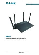
background image

User Manual

DIR-878

AC1900 MU-MIMO Wi-Fi Gigabit Router

March 2019

Summary of Contents for DIR-878

Page 1: ...User Manual DIR 878 AC1900 MU MIMO Wi Fi Gigabit Router March 2019 ...

Page 2: ...e Structure 29 Summary Page 29 Home Page 31 Menu Sections 32 Notifications 33 Chapter 4 Configuring via Web based Interface 34 Initial Configuration Wizard 34 Selecting Operation Mode 36 Changing LAN IPv4 Address 39 Wi Fi Client 40 Configuring WAN Connection 42 Static IPv4 Connection 43 Static IPv6 Connection 44 PPPoE IPv6 PPPoE PPPoE Dual Stack PPPoE Dynamic IP PPPoE Dual Access Connections 45 PP...

Page 3: ...ement 105 WPS 106 Using WPS Function via Web based Interface 108 Using WPS Function without Web based Interface 109 WMM 110 Client 113 Additional 116 MAC Filter 119 Roaming 121 Advanced 123 VLAN 124 DNS 126 DDNS 128 NSG 130 Ports Settings 132 Redirect 135 Routing 136 TR 069 Client 138 Remote Access 140 UPnP IGD 142 UDPXY 143 IGMP 145 ALG Passthrough 146 IPsec 148 Firewall 154 IP Filter 154 Virtual...

Page 4: ...nual Yandex DNS 180 Settings 180 Devices and Rules 182 SkyDNS 184 Settings 184 Devices 186 Chapter 5 Operation Guidelines 188 Safety Rules and Conditions 188 Wireless Installation Considerations 189 Chapter 6 Abbreviations and Acronyms 190 Page 4 of 191 ...

Page 5: ... Guide A reference to a document Change A name of a menu menu item control field checkbox drop down list button etc 192 168 0 1 Data that you should enter in the specified field Information An important note Document Structure Chapter 1 describes the purpose and structure of the document Chapter 2 gives an overview of the router s hardware and software features describes its appearance and the pac...

Page 6: ...the router will stay online Multi user MIMO technology allows to distribute the router s resources to let multiple wireless clients use the Wi Fi network efficiently keeping high rates for HD media streaming lag free gaming and fast transfer of large files Transmit Beamforming technology allows to flexibly change the antennas radiation pattern and to redistribute the signal directly to wireless de...

Page 7: ...y switch DIR 878 to one of the following modes router for connection to a wired or wireless ISP access point repeater or client and then configure all needed setting for operation in the selected mode in several simple steps Also DIR 878 supports configuration and management via mobile application for Android and iPhone smartphones You can simply update the firmware the router itself finds approve...

Page 8: ... Static IPv6 Dynamic IPv6 PPPoE Static IP PPPoE Dual Access PPPoE Dynamic IP PPPoE Dual Access PPTP L2TP Static IP PPTP L2TP Dynamic IP Network functions Support of IEEE 802 1X for Internet connection DHCP server relay Stateful Stateless mode for IPv6 address assignment IPv6 prefix delegation Automatic obtainment of LAN IP address for access point repeater client modes DNS relay Dynamic DNS Static...

Page 9: ...ion on new firmware version Saving restoring configuration to from file Support of logging to remote host Automatic synchronization of system time with NTP server and manual time date setup Ping utility Traceroute utility TR 069 client Wireless Module Parameters Standards IEEE 802 11a n ac IEEE 802 11b g n Frequency range 2400 2483 5MHz 5150 5350MHz 5650 5725MHz Wireless connection security WEP WP...

Page 10: ... 5GHz 15dBm at MCS0 7 802 11ac typical at room temperature 25 C 15dBm at MCS0 9 Receiver sensitivity 802 11a 96dBm at 6Mbps 78dBm at 54Mbps 802 11b 96dBm at 1Mbps 90dBm at 11Mbps 802 11g 95dBm at 6Mbps 76dBm at 54Mbps 802 11n 2 4GHz HT20 95dBm at MCS0 76dBm at MCS7 2 4GHz HT40 92dBm at MCS0 72dBm at MCS7 5GHz HT20 95dBm at MCS0 76dBm at MCS7 5GHz HT40 93dBm at MCS0 73dBm at MCS7 802 11ac VHT20 96d...

Page 11: ... OFDM 802 11n BPSK QPSK 16QAM 64QAM 256QAM with OFDM 802 11ac BPSK QPSK 16QAM 64QAM up to 256QAM with OFDM Physical Parameters Dimensions L x W x H 259 x 184 x 46 mm 10 8 x 7 24 x 1 81 in Weight 565 g 1 25 lb Operating Environment Power Output 12V DC 1 5A Temperature Operating from 0 to 40 C Storage from 20 to 65 C Humidity Operating from 10 to 90 non condensing Storage from 5 to 95 non condensing...

Page 12: ...g green The default wired WAN connection is active Slow blinking green The firmware is being updated Blinking orange The default wired WAN connection is off or there are no WAN connections created No light The WAN cable is not connected WLAN 2 4G WLAN 5G Solid green The router s WLAN of the relevant band is on Fast blinking green Data transfer through the Wi Fi network of the relevant band Blinkin...

Page 13: ...aults To restore the factory defaults push the button with the device turned on hold it for 10 seconds and then release the button WPS A button to set up wireless connection the WPS function To use the WPS function with the device turned on push the button hold it for 2 seconds and release The WLAN 2 4G and WLAN 5G LEDs should start blinking WiFi A button to enable disable wireless network To disa...

Page 14: ...8 AC1900 MU MIMO Wi Fi Gigabit Router User Manual Overview Port Description POWER A button to turn the router on off The device is also equipped with four external non detachable Wi Fi antennas Page 14 of 191 ...

Page 15: ...78 Power adapter DC 12V 1 5A Ethernet cable Quick Installation Guide brochure The User Manual and Quick Installation Guide documents are available on D Link website see www dlink ru Using a power supply with a different voltage rating than the one included will cause damage and void the warranty for this product Page 15 of 191 ...

Page 16: ...10 and later Microsoft Edge 20 10240 and later Mozilla Firefox 44 and later Opera 35 and later For successful operation JavaScript should be enabled on the web browser Make sure that JavaScript has not been disabled by other software such as virus protection or web user security packages running on your computer Wired or Wireless NIC Ethernet or Wi Fi Adapter Any computer that uses the router shou...

Page 17: ...he back panel of the router and the Ethernet port of your PC 2 Connect the power cord to the power connector port on the back panel of the router then plug the power adapter into an electrical outlet or power strip 3 Turn on the router by pressing the POWER button on its back panel Then make sure that your PC is configured to obtain an IP address automatically as DHCP client Page 17 of 191 ...

Page 18: ... proceed to the Control Panel window 2 Select the Network and Sharing Center section If the Control Panel has the category view the Category value is selected from the View by drop down list in the top right corner of the window choose the View network status and tasks line under the Network and Internet section Figure 3 The Control Panel window Page 18 of 191 ...

Page 19: ...MIMO Wi Fi Gigabit Router User Manual Installation and Connection 3 In the menu located on the left part of the window select the Change adapter settings line Figure 4 The Network and Sharing Center window Page 19 of 191 ...

Page 20: ...abit Router User Manual Installation and Connection 4 In the opened window right click the relevant Local Area Connection icon and select the Properties line in the menu displayed Figure 5 The Network Connections window Page 20 of 191 ...

Page 21: ...nual Installation and Connection 5 In the Local Area Connection Properties window on the Networking tab select the Internet Protocol Version 4 TCP IPv4 line Click the Properties button Figure 6 The Local Area Connection Properties window Page 21 of 191 ...

Page 22: ...ure that the Obtain an IP address automatically and Obtain DNS server address automatically choices of the radio buttons are selected Click the OK button Figure 7 The Internet Protocol Version 4 TCP IPv4 Properties window 7 Click the OK button in the connection properties window Page 22 of 191 ...

Page 23: ...ter by pressing the POWER button on its back panel 3 Make sure that your Wi Fi adapter is on As a rule modern notebooks with built in wireless NICs are equipped with a button or switch that turns on off the wireless adapter refer to your PC documents If your PC is equipped with a pluggable wireless NIC install the software provided with your Wi Fi adapter Then make sure that your Wi Fi adapter is ...

Page 24: ...e top right corner of the window choose the View network status and tasks line under the Network and Internet section Figure 8 The Control Panel window 3 In the menu located on the left part of the window select the Change adapter settings line 4 In the opened window right click the relevant Wireless Network Connection icon Make sure that your Wi Fi adapter is on then select the Properties line in...

Page 25: ... the OK button Figure 9 The Internet Protocol Version 4 TCP IPv4 Properties window 7 Click the OK button in the connection properties window 8 To open the list of available wireless networks select the icon of the wireless network connection and click the Connect To button or left click the network icon in the notification area located on the right side of the taskbar Figure 10 The notification ar...

Page 26: ...ned window enter the network key see WPS PIN on the barcode label on the bottom panel of the device in the Security key field and click the OK button 11 Wait for about 20 30 seconds After the connection is established the network icon will be displayed as the signal level scale If you perform initial configuration of the router via Wi Fi connection note that immediately after changing the wireless...

Page 27: ... the address bar of the web browser enter the domain name of the router by default dlinkrouter local with a dot at the end and press the Enter key Also you can enter the IP address of the device by default 192 168 0 1 Figure 12 Connecting to the web based interface of the DIR 878 device If the error The page cannot be displayed or Unable to display the page Could not connect to remote server occur...

Page 28: ...terface the login page opens Enter the username admin in the Username field and the password you specified in the Password field then click the LOGIN button Figure 14 The login page If you enter a wrong password several times the web based interface will be blocked for a while Please wait for one minute and reenter the password you specified Page 28 of 191 ...

Page 29: ...MO Wi Fi Gigabit Router User Manual Installation and Connection Web based Interface Structure Summary Page On the Summary page detailed information on the device state is displayed Figure 15 The summary page Page 29 of 191 ...

Page 30: ...ee the Initial Configuration Wizard section page 34 The Wi Fi 2 4 GHz and Wi Fi 5 GHz sections display data on the state of the device s wireless network its name and the authentication type and availability of an additional wireless network in the relevant band In the WAN section data on the type and status of the existing WAN connection are displayed In the LAN section the IPv4 and IPv6 address ...

Page 31: ...anual Installation and Connection Home Page The Home page displays links to the most frequently used pages with device s settings Figure 16 The Home page Other settings of the router are available in the menu in the left part of the page Page 31 of 191 ...

Page 32: ...f the Wi Fi section are designed for specifying all needed settings of the router s wireless network for the description of the pages see the Wi Fi section page 97 The pages of the Advanced section are designed for configuring additional parameters of the router for the description of the pages see the Advanced section page 123 The pages of the Firewall section are designed for configuring the fir...

Page 33: ...tion Notifications The router s web based interface displays notifications in the top right part of the page Figure 17 The web based interface notifications Click the icon displaying the number of notifications to view the complete list and click the relevant button Page 33 of 191 ...

Page 34: ...on and wait until the factory default settings are restored Figure 18 Restoring the default settings in the Wizard If you perform initial configuration of the router via Wi Fi connection please make sure that you are connected to the wireless network of DIR 878 see the WLAN name SSID on the barcode label on the bottom panel of the device and click the NEXT button Figure 19 Checking connection to t...

Page 35: ...web based interface To do this click the ADVANCED SETTINGS button On the opened page change the default settings specify the administrator password in the Admin password and Password confirmation fields and the name of the wireless network in the 2 4GHz and 5GHz bands in the Network name 2 4 GHz SSID and Network name 5 GHz SSID fields correspondingly Then click the APPLY button Figure 22 Changing ...

Page 36: ... your own password for access to the web based interface of the device Figure 23 Selecting an operation mode The Router mode In order to connect your device to a wireless ISP WISP on the Device mode page from the Connection method list select the Wi Fi value Then from the Work mode list select the WISP Repeater value In this mode you can connect your device to another access point configure a WAN ...

Page 37: ...r own password for access to the web based interface of the device Figure 25 Selecting an operation mode The Access point mode In order to connect your device to a wireless router for extending the range of the existing wireless network on the Device mode page from the Connection method list select the Wi Fi value Then from the Work mode list select the Repeater value In this mode you can change t...

Page 38: ...ge from the Connection method list select the Wi Fi value Then from the Work mode list select the Client value In this mode you can change the LAN IP address connect your device to another access point and set your own password for access to the web based interface of the device Figure 27 Selecting an operation mode The Client mode When the operation mode is selected click the NEXT button Page 38 ...

Page 39: ...n access the web based interface using the domain name by default dlinkrouter local with a dot at the end If you want to manually assign the LAN IPv4 address for DIR 878 do not select the Automatic obtainment of IPv4 address checkbox and fill in the IP address and Netmask fields and if needed the Gateway IP address field Make sure that the assigned address does not coincide with the LAN IPv4 addre...

Page 40: ...ency band list and enter the network name in the Network name SSID field Then select a needed value from the Network authentication list and then if needed enter the password in the relevant field When the Open or WEP authentication type is selected the following settings are displayed on the page Parameter Description Enable encryption WEP For Open authentication type only The checkbox activating...

Page 41: ...uthentication type is selected the following fields are displayed Parameter Description Password PSK A password for WPA encryption Click the Show icon to display the entered password Encryption type An encryption method TKIP AES or TKIP AES 3 Click the NEXT button to continue or click the BACK button to return to the previous page Page 41 of 191 ...

Page 42: ... your connection Otherwise contact your ISP 1 On the Internet connection type page from the Connection type list select the connection type used by your ISP and fill in the fields displayed on the page 2 Specify the settings necessary for the connection of the selected type 3 If your ISP uses MAC address binding select the Clone MAC address of your device checkbox 4 If the Internet access is provi...

Page 43: ...outer User Manual Configuring via Web based Interface Static IPv4 Connection Figure 30 The page for configuring Static IPv4 WAN connection Fill in the following fields IP address Netmask Gateway IP address and DNS IP address Page 43 of 191 ...

Page 44: ...Router User Manual Configuring via Web based Interface Static IPv6 Connection Figure 31 The page for configuring Static IPv6 WAN connection Fill in the following fields IP address Prefix Gateway IP address and DNS IP address Page 44 of 191 ...

Page 45: ...mic IP PPPoE Dual Access Connections Figure 32 The page for configuring PPPoE WAN connection In the Username field enter the login and in the Password field enter the password provided by your ISP Click the Show icon to display the entered password If authorization is not required select the Without authorization checkbox Page 45 of 191 ...

Page 46: ...Static IP PPPoE Dual Access WAN connection In the Username field enter the login and in the Password field enter the password provided by your ISP Click the Show icon to display the entered password If authorization is not required select the Without authorization checkbox Also fill in the following fields IP address Netmask Gateway IP address and DNS IP address Page 46 of 191 ...

Page 47: ...TP Dynamic IP WAN connection In the Username field enter the login and in the Password field enter the password provided by your ISP Click the Show icon to display the entered password If authorization is not required select the Without authorization checkbox In the VPN server address field enter the IP or URL address of the PPTP or L2TP authentication server Page 47 of 191 ...

Page 48: ...eld enter the login and in the Password field enter the password provided by your ISP Click the Show icon to display the entered password If authorization is not required select the Without authorization checkbox In the VPN server address field enter the IP or URL address of the PPTP or L2TP authentication server Also fill in the following fields IP address Netmask Gateway IP address and DNS IP ad...

Page 49: ... Password field specify your own password for access to the wireless network or leave the value suggested by the router WPS PIN of the device see the barcode label 3 If the router is used as a Wi Fi client you can specify the same parameters of the wireless network as specified for the network to which you are connecting To do this click the USE button available for the Repeater mode only 4 You ca...

Page 50: ... name for the guest wireless network or leave the value suggested by the router 7 If you want to create a password for access to the guest wireless network deselect the Open network checkbox and fill in the Password field 8 If you want to limit the bandwidth of the guest wireless network select the Enable shaping checkbox and fill in the Shaping field 9 Click the NEXT button to continue or click t...

Page 51: ... IPTV page select the Is an STB connected to the device checkbox Figure 38 The page for selecting a LAN port to connect an IPTV set top box 2 Select a free LAN port for connecting your set top box 3 If the IPTV service is provided via a VLAN channel select the Use VLAN ID checkbox and fill in the VLAN ID field 4 Click the NEXT button to continue or click the BACK button to specify other settings P...

Page 52: ...device checkbox Figure 39 The page for selecting a LAN port to connect an VoIP phone 6 Select a free LAN port for connecting your IP phone 7 If the VoIP service is provided via a VLAN channel select the Use VLAN ID checkbox and fill in the VLAN ID field 8 Click the NEXT button to continue or click the BACK button to specify other settings Page 52 of 191 ...

Page 53: ...d for the administrator account In case of losing the new password you can access the settings of the router only after restoring the factory default settings via the hardware RESET button This procedure wipes out all settings that you have configured for your router Click the NEXT button to continue or click the BACK button to return to the previous page On the next page check all specified setti...

Page 54: ...H button If problems appeared when connecting to the Internet click the CHECK AGAIN button to recheck the state of the WAN connection If problems of connection have not been solved contact the technical support of your ISP as a rule the technical support phone is provided with the agreement or the D Link technical support the phone number is displayed on the Summary page To specify other settings ...

Page 55: ...t top box or IP phone Contact your ISP to clarify if you need to configure DIR 878 in order to use these devices To start the Wizard on the Home page select the Connection of Multimedia Devices section If you need to select a port or wireless interface in order to use an additional device left click the relevant element in the LAN section the selected element will be marked with a frame Then click...

Page 56: ...ened window specify a name of the connection for easier identification in the Name field you can specify any name Specify the VLAN ID provided by your ISP and click the SAVE button Then in the LAN section from the Bridged with drop down list of the element corresponding to the LAN port or wireless interface to which the additional device is connected select the created connection Click the APPLY b...

Page 57: ...rame will disappear and click the APPLY button To deselect the port or wireless interface in the advanced mode select the No value from the Bridged with drop down list of the element corresponding to the needed LAN port or interface Then in the WAN section select the connection via VLAN which will not be used any longer and click the DELETE button Then click the APPLY button Page 57 of 191 ...

Page 58: ...On the Statistics Network Statistics page you can view statistics for all connections existing in the system WAN connections LAN WLAN For each connection the following data are displayed name and state when the connection is on its name is highlighted in green when the connection is off its name is highlighted in red IP address and subnet mask and volume of data received and transmitted with incre...

Page 59: ...HCP The Statistics DHCP page displays the information on computers that have been identified by hostnames and MAC addresses and have got IP addresses from the DHCP server of the device as well as the IP address expiration periods the lease time Figure 46 The Statistics DHCP page Page 59 of 191 ...

Page 60: ...Configuring via Web based Interface Routing Table The Statistics Routing Table page displays the information on routes The table contains destination IP addresses gateways subnet masks and other data Figure 47 The Statistics Routing Table page Page 60 of 191 ...

Page 61: ... The Statistics Clients and Session page For each device the following data are displayed the IP address the MAC address and the network interface to which the device is connected To view the information on current sessions of a device select this device in the table On the opened page the following data for each session of the selected device will be displayed the protocol for network packet tran...

Page 62: ...s The Statistics Multicast Groups page displays addresses of active multicast groups including IPTV channels and groups for transferring service information to which the device is subscribed and the interface through which the device is subscribed Figure 49 The Statistics Multicast Groups page Page 62 of 191 ...

Page 63: ...n existing connection click the EDIT button On the opened page on the Basic tab the mandatory settings of this connection will be displayed To view all available settings of the WAN connection go to the All Settings tab Change the needed parameters and click the APPLY button To disconnect a connection and establish it again click the RECONNECT button To remove an existing connection and create a n...

Page 64: ...ct a connection and establish it again select the checkbox located to the left of the relevant line in the table and click the RECONNECT button To remove a connection in the Connections List section select the checkbox located to the left of the relevant line in the table and click the DELETE button Also you can remove a connection on the editing page To allow multicast traffic e g streaming video...

Page 65: ...alue from the Connection type drop down list and specify the needed values Figure 52 The page for creating a new Static IPv4 connection Selecting a connection type Parameter Description Enable connection Move the switch to the right to enable the connection Move the switch to the left to disable the connection Connection name Available for the advanced mode only A name for the connection for easie...

Page 66: ...istered by your ISP upon concluding the agreement To set the MAC address of the network interface card of the computer that is being used to configure the router at the moment as the MAC address of the WAN interface move the Clone MAC address of your NIC switch to the right When the switch is moved to the right the field is unavailable for editing To set the router s MAC address click the RESTORE ...

Page 67: ...ection Parameter Description Authorization via 802 1x Protocol Enable authorization via 802 1x protocol Move the switch to the right to allow authorization in the ISP s network via the 802 1x protocol Authentication method Select a needed authentication method from the drop down list Login Enter the username provided by your ISP Password Enter the password provided by your ISP Page 67 of 191 ...

Page 68: ...y this WAN connection Primary DNS Secondary DNS Enter addresses of the primary and secondary DNS servers in the relevant fields For Dynamic IPv4 type Obtain DNS server addresses automatically Move the switch to the right to configure automatic assignment of DNS server addresses Upon that the Primary DNS and Secondary DNS fields are not available for editing Primary DNS Secondary DNS Enter addresse...

Page 69: ...or example against attempts to get information about the LAN devices or to hack a device from the LAN For security reasons it is recommended not to disable this function RIP Move the switch to the right to allow using RIP for this connection Ping If the switch is moved to the right the router responds to ping requests from the external network through this connection For security reasons it is rec...

Page 70: ...alue from the Connection type drop down list and specify the needed values Figure 57 The page for creating a new Static IPv6 connection Selecting a connection type Parameter Description Enable connection Move the switch to the right to enable the connection Move the switch to the left to disable the connection Connection name Available for the advanced mode only A name for the connection for easie...

Page 71: ...istered by your ISP upon concluding the agreement To set the MAC address of the network interface card of the computer that is being used to configure the router at the moment as the MAC address of the WAN interface move the Clone MAC address of your NIC switch to the right When the switch is moved to the right the field is unavailable for editing To set the router s MAC address click the RESTORE ...

Page 72: ... Get IPv6 Select a method for IPv6 address assignment from the drop down list or leave the Automatically value Gateway by SLAAC Move the switch to the right to automatically assign the IPv6 gateway address with help of SLAAC Stateless Address Autoconfiguration Gateway IPv6 address The address of the IPv6 gateway The field is available for editing if the Gateway by SLAAC switch is moved to the left...

Page 73: ...hack a device from the LAN For security reasons it is recommended not to disable this function RIP Move the switch to the right to allow using RIP for this connection Ping If the switch is moved to the right the router responds to ping requests from the external network through this connection For security reasons it is recommended to disable this function Isolate connection If the switch is moved...

Page 74: ...m the Connection type drop down list and specify the needed values Figure 61 The page for creating a new PPPoE connection Selecting a connection type Parameter Description Enable connection Move the switch to the right to enable the connection Move the switch to the left to disable the connection Connection name Available for the advanced mode only A name for the connection for easier identificati...

Page 75: ...ered by your ISP upon concluding the agreement To set the MAC address of the network interface card of the computer that is being used to configure the router at the moment as the MAC address of the WAN interface move the Clone MAC address of your NIC switch to the right When the switch is moved to the right the field is unavailable for editing To set the router s MAC address click the RESTORE DEF...

Page 76: ...the Internet Click the Show icon to display the entered password Service name The name of the PPPoE authentication server MTU The maximum size of units transmitted by the interface Authentication protocol Select a required authentication method from the drop down list or leave the AUTO value Keep Alive Move the switch to the right if you want the router to keep you connected to your ISP even when ...

Page 77: ...ld specify a period of inactivity in seconds after which the connection should be terminated Static IP address Fill in the field if you want to use a static IP address to access the Internet PPP IP extension This option is used by some ISPs Contact your ISP to clarify if this option needs to be enabled If it is required move the switch to the right PPP debug Move the switch to the right if you wan...

Page 78: ...equests from the external network through this connection For security reasons it is recommended to disable this function Isolate connection If the switch is moved to the right the router uses an alternate routing table for this connection Enable this function only when your ISP requires this When all needed settings are configured click the APPLY button After clicking the button the window for cr...

Page 79: ... from the Connection type drop down list and specify the needed values Figure 65 The page for creating a new PPTP connection Selecting a connection type Parameter Description Enable connection Move the switch to the right to enable the connection Move the switch to the left to disable the connection Connection name Available for the advanced mode only A name for the connection for easier identific...

Page 80: ...ter a username and password to access the Internet Username A username login to access the Internet Password A password to access the Internet Click the Show icon to display the entered password VPN server address The IP or URL address of the PPTP or L2TP authentication server MTU The maximum size of units transmitted by the interface Authentication protocol Select a required authentication method...

Page 81: ... the switch is moved to the right the LCP interval and LCP fails fields are available Specify the required values Dial on demand Move the switch to the right if you want the router to establish connection to the Internet on demand In the Maximum idle time field specify a period of inactivity in seconds after which the connection should be terminated Extra options Advanced options of the pppd daemo...

Page 82: ...s to ping requests from the external network through this connection For security reasons it is recommended to disable this function Isolate connection If the switch is moved to the right the router uses an alternate routing table for this connection Enable this function only when your ISP requires this When all needed settings are configured click the APPLY button After clicking the button the wi...

Page 83: ... value from the Connection type drop down list and specify the needed values Figure 68 The page for creating a new PPPoE IPv6 connection Selecting a connection type Parameter Description Enable connection Move the switch to the right to enable the connection Move the switch to the left to disable the connection Connection name Available for the advanced mode only A name for the connection for easi...

Page 84: ...stered by your ISP upon concluding the agreement To set the MAC address of the network interface card of the computer that is being used to configure the router at the moment as the MAC address of the WAN interface move the Clone MAC address of your NIC switch to the right When the switch is moved to the right the field is unavailable for editing To set the router s MAC address click the RESTORE D...

Page 85: ...ss the Internet Click the Show icon to display the entered password Service name The name of the PPPoE authentication server MTU The maximum size of units transmitted by the interface Authentication protocol Select a required authentication method from the drop down list or leave the AUTO value Keep Alive Move the switch to the right if you want the router to keep you connected to your ISP even wh...

Page 86: ...od of inactivity in seconds after which the connection should be terminated Static IP address For the PPPoE Dual Stack type only Fill in the field if you want to use a static IP address to access the Internet PPP IP extension This option is used by some ISPs Contact your ISP to clarify if this option needs to be enabled If it is required move the switch to the right PPP debug Move the switch to th...

Page 87: ...ddress with help of SLAAC Stateless Address Autoconfiguration Gateway IPv6 address The address of the IPv6 gateway The field is available for editing if the Gateway by SLAAC switch is moved to the left Obtain DNS server addresses automatically Move the switch to the right to configure automatic assignment of IPv6 DNS server addresses Upon that the Primary IPv6 DNS server and Secondary IPv6 DNS ser...

Page 88: ...ices is enabled for example against attempts to get information about the LAN devices or to hack a device from the LAN For security reasons it is recommended not to disable this function RIP Move the switch to the right to allow using RIP for this connection Ping If the switch is moved to the right the router responds to ping requests from the external network through this connection For security ...

Page 89: ... the drop down list Static the IP address subnet mask and the gateway IP address are assigned manually Dynamic the router automatically obtains these parameters from the LAN DHCP server or from the router to which it connects IP address The IP address of the router in the local subnet By default the following value is specified 192 168 0 1 Mask The mask of the local subnet By default the following...

Page 90: ...When this value is selected the External DHCP server IP and Option 82 Remote ID fields are displayed on the tab Start IP The start IP address of the address pool used by the DHCP server to distribute IP addresses to clients End IP The end IP address of the address pool used by the DHCP server to distribute IP addresses to clients Lease time The lifetime of IP addresses leased by the DHCP server At...

Page 91: ...mic IP Addresses section the DHCP server value is selected from the Mode of dynamic IP address assignment drop down list Figure 75 The section for creating MAC IPv4 pairs To create a MAC IPv4 pair click the ADD button In the opened window in the IP address field enter an IPv4 address which will be assigned to the device from the LAN then in the MAC address field enter the MAC address of this devic...

Page 92: ...tic an IPv6 address and a prefix are specified manually Prefix delegation the router requests a prefix to configure an IPv6 address from a delegating router IPv6 address The IPv6 address of the router in the local subnet By default the following value is specified fd01 1 The field is available for editing if the Static value is selected from the Mode of local IPv6 address assignment drop down list...

Page 93: ...he range specified in the Start IPv6 and End IPv6 fields Stateless clients themselves configure IPv6 addresses using the prefix Start IPv6 The start IPv6 address of the address pool used by the DHCPv6 server to distribute addresses to clients End IPv6 The end IPv6 address of the address pool used by the DHCPv6 server to distribute addresses to clients Lease time The lifetime of IPv6 addresses prov...

Page 94: ...ed to the device from the LAN then in the MAC address field enter the MAC address of this device In the Hostname field specify a network name of the device for easier identification optional Click the APPLY button In order to view MAC addresses of the devices connected to the router at the moment click the CLIENTS LIST button In the opened window select the needed device and click the OK button To...

Page 95: ...ameter Description Basic connection From the drop down list select a WAN connection which will be used as the main one Backup connection From the drop down list select a WAN connection which will be used as the reserve one Test host An IP address that the router will check for availability via ICMP ping mechanism Check interval A time period in seconds between attempts to check the status of the m...

Page 96: ...ion Number of inspections of inactive connection A number of requests that will be sent in order to analyze the status of the main connection when the connection is inactive the router uses the reserve connection as a default gateway When all needed settings are configured click the APPLY button Page 96 of 191 ...

Page 97: ...or your wireless network Basic Settings In the Wi Fi Basic Settings section you can change basic parameters for the wireless interface of the router and configure the basic and additional wireless networks To configure the 2 4GHz band or 5GHz band go to the relevant tab Figure 80 Basic settings of the wireless LAN in the 2 4GHz band Page 97 of 191 ...

Page 98: ...oose the channel with the least interference Enable additional channels If the switch is moved to the left the device automatically selects one of available standard channels To use additional channels the 12th and 13th in the 2 4 GHz band the 100th and higher in the 5 GHz band move the switch to the right Channel The wireless channel number Left click to open the window for selecting a channel th...

Page 99: ...of the basic wireless network in the Wi Fi Network section change the needed parameters and click the APPLY button Also you can create an additional wireless network To do this click the ADD WI FI NETWORK button On the opened page specify the relevant parameters Figure 81 Creating a wireless network Page 99 of 191 ...

Page 100: ...e switch to the right to limit the maximum bandwidth of the wireless network In the Shaping field displayed specify the maximum value of speed Mbit s Move the switch to the left not to limit the maximum bandwidth Broadcast wireless network If the switch is moved to the left devices cannot connect to the wireless network Upon that the router can connect to another access point as a wireless client ...

Page 101: ...a shared key with WEP encryption This authentication type is not available when a mode supporting 802 11n or 802 11ac devices is selected from the Wireless mode drop down list on the Wi Fi Basic Settings page WPA WPA based authentication using a RADIUS server WPA PSK WPA based authentication using a PSK WPA2 WPA2 based authentication using a RADIUS server WPA2 PSK WPA2 based authentication using a...

Page 102: ...ble encryption WEP For Open authentication type only To activate WEP encryption move the switch to the right Upon that the Default key ID drop down list the Encryption key WEP as HEX switch and four Encryption key fields are displayed on the page Default key ID The number of the key from first to fourth which will be used for WEP encryption Encryption key WEP as HEX Move the switch to the right to...

Page 103: ...ription Password PSK A password for WPA encryption The password can contain digits Latin letters uppercase and or lowercase and other characters available in the US keyboard layout 4 Click the Show icon to display the entered password Encryption type An encryption method TKIP AES or TKIP AES Group key update interval The time period in seconds at the end of which a new key for WPA encryption is ge...

Page 104: ...he password which the router uses for communication with the RADIUS server the value of this parameter is specified in the RADIUS server settings Encryption type An encryption method TKIP AES or TKIP AES Group key update interval The time period in seconds at the end of which a new key for WPA encryption is generated When the value 0 is specified for this field the key is not renewed When you have...

Page 105: ...86 The page for managing the wireless clients If you want to disconnect a wireless device from your WLAN select the checkbox in the line containing the MAC address of this device and click the DISCONNECT button To view the latest data on the devices connected to the WLAN click the REFRESH button To view the latest data on a connected device left click the line containing the MAC address of this de...

Page 106: ...ust support the WPS function The WPS function allows adding devices only to the basic wireless network of the router Before using the function you need to configure one of the following authentication types Open with no encryption WPA2 PSK or WPA PSK WPA2 PSK mixed with the AES encryption method When other security settings are specified controls of the WPS page on the tab of the relevant band are...

Page 107: ...cally the network authentication type will be changed to WPA2 PSK Default PIN code The PIN code of the router This parameter is used when connecting the router to a registrar to set the parameters of the WPS function Network name SSID The name of the router s wireless network Network authentication The network authentication type specified for the wireless network Encryption The encryption type sp...

Page 108: ...AN 6 Right after that enter the PIN code specified on the cover of the wireless device or in its software in the PIN code field 7 Click the CONNECT button in the web based interface of the router To connect to the basic wireless network via the PBC method of the WPS function follow the next steps 1 Click the ENABLE WPS button 2 In the WPS Control section click the ESTABLISH CONNECTION button 3 In ...

Page 109: ...the ENABLE WPS button 3 Save the settings and close the web based interface click the Logout line of the menu Later you will be able to add wireless devices to the WLAN by pressing the WPS button of the router 1 Select the PBC method in the software of the wireless device that you want to connect to the router s WLAN 2 Click the relevant button in the software or press the WPS button on the cover ...

Page 110: ... are displayed on the page Figure 88 The page for configuring the WMM function All needed settings for the WMM function are specified in the device s system It is recommended not to change the default values The WMM function allows assigning priorities for four Access Categories AC BK Background low priority traffic print jobs file downloads etc BE Best Effort traffic from legacy devices or device...

Page 111: ...ximum Both fields influence time delays for the relevant Access Category The CWMax field value should not be lower than the CWMin field value The lower the difference between the CWMax field value and the CWMin field value the higher is the Access Category priority TXOP Transmission Opportunity The higher the value the higher is the Access Category priority ACM Admission Control Mandatory If the s...

Page 112: ...DIR 878 AC1900 MU MIMO Wi Fi Gigabit Router User Manual Configuring via Web based Interface Click the SAVE button To disable the WMM function click the DISABLE button Page 112 of 191 ...

Page 113: ...age for configuring the client mode To configure the router as a client move the Enable switch to the right Upon that the following fields are displayed on the page Parameter Description Broadcast wireless network 2 4 GHz Broadcast wireless network 5 GHz If the switch is moved to the left devices cannot connect to the router s WLAN Upon that the router can connect to another access point as a wire...

Page 114: ...If needed fill in the BSSID field Then select the needed type of authentication from the Network authentication drop down list When the Open or WEP authentication type is selected the following settings are displayed on the page Parameter Description Enable encryption WEP For Open authentication type only To activate WEP encryption move the switch to the right Upon that the Default key ID drop dow...

Page 115: ...figured the parameters click the APPLY button When connecting to a wireless access point the wireless channel of DIR 878 will switch to the channel of the access point to which you have connected In addition the Connection Information section in which you can view the connection status and the network basic parameters is displayed If you want to connect to the WISP network after configuring the de...

Page 116: ...l On page of the Wi Fi Additional section you can define additional parameters for the WLAN of the router To configure the 2 4GHz band or 5GHz band go to the relevant tab Changing parameters presented on this page may negatively affect your WLAN Figure 91 Additional settings of the WLAN Page 116 of 191 ...

Page 117: ...uter to automatically choose the most suitable channel bandwidth 20MHz or 40MHz for the connected devices this setting can substantially lower the data transfer rate of your wireless network The switch is displayed when the 20 40 MHz value is selected from the Bandwidth drop down list TX power The transmit power in percentage terms of the router B G protection Available on the 2 4 GHz tab The 802 ...

Page 118: ...nced IGMP page Enable TX Beamforming TX Beamforming is the signal processing directing technique which helps to support a high enough transfer rate in the areas with difficult conditions for the signal propagation Move the switch to the right to improve the signal quality Beacon period The time interval in milliseconds between packets sent to synchronize the wireless network RTS threshold The mini...

Page 119: ...ices which will not be allowed to access the WLAN It is recommended to configure the Wi Fi MAC filter through a wired connection to DIR 878 Figure 92 The page for configuring the MAC filter for the wireless network By default the Wi Fi MAC filter is disabled To configure the MAC filter first you need to create rules specify MAC addresses of devices for which the specified filtering modes will be a...

Page 120: ...ters section left click the needed rule In the opened window change the settings and click the SAVE button To remove the rule from the page in the Filters section select the checkbox located to the left of the relevant rule and click the DELETE button After creating the rules you need to configure the filtering modes To open the basic or additional wireless network for the devices which MAC addres...

Page 121: ...enable the function click the ENABLE button Upon that the following settings are available on the page Parameter Description Port The number of the port used for data exchange between access points routers Use multicast for service data exchange Move the switch to the right in order to use multicast traffic for service data exchange between access points routers This setting is needed if the devic...

Page 122: ...r signal level Threshold value of connection quality The signal strength upon which the access point router disconnects the client from its wireless network regardless of the signal levels of other devices This value should not be greater than the value specified in the field Minimum level of connection quality Dead zone This parameter is used for calculation of the signal strength upon which the ...

Page 123: ...d and duplex mode for each Ethernet port of the router configure notifications on the reason of the Internet connection failure define static routes configure TR 069 client create rules for remote access to the web based interface enable the UPnP IGD protocol enable the built in UDPXY application for the router allow the router to use IGMP allow the router to use RTSP enable the SIP ALG the PPPoE ...

Page 124: ... this group Figure 95 The Advanced VLAN page If you want to create a group including LAN ports of the router first delete relevant records from the lan group on this page To do this select the lan group On the opened page in the Untagged Ports section deselect the checkbox located to the left of the relevant port and click the APPLY button To create a new group for VLAN click the ADD button Figure...

Page 125: ...section is not displayed Bridge The group of this type is a transparent connection between an internal port and an external connection It is mostly used to connect IPTV set top boxes VLAN ID An identifier of the VLAN to which this group of ports will be assigned QoS A priority tag for the transmitted traffic Untagged Ports The section includes the ports that can be added to the group To add a port...

Page 126: ...ent of DNS servers addresses move the Manual switch to the left use the DNS IPv4 section for IPv4 and the DNS IPv6 section for IPv6 Then move the Default gateway switch to the left and from the Interface drop down list select a WAN connection which will be used to obtain addresses of DNS servers automatically If you want the router to use the default WAN connection to obtain addresses of DNS serve...

Page 127: ...this select the relevant IP address from the drop down list the field will be filled in automatically In the Name field specify the domain name to which the specified IP address will correspond Click the SAVE button To edit an existing record in the Hosts section select the relevant line in the table In the opened window change the needed parameters and click the SAVE button To remove a record in ...

Page 128: ...e opened page you can specify the following parameters Parameter Description Hostname The full domain name registered at your DDNS provider DDNS service Select a DDNS provider from the drop down list Username The username to authorize for your DDNS provider Password The password to authorize for your DDNS provider Click the Show icon to display the entered password Update period An interval in min...

Page 129: ...arameters of the existing DDNS service select the relevant line in the table On the opened page change the needed parameters and click the SAVE button To remove an existing DDNS service select the checkbox located to the left of the relevant line in the table and click the DELETE button Page 129 of 191 ...

Page 130: ...k the ADD WI FI NETWORK button On the opened page specify the relevant parameters and move the Enable NSG service switch to the right Click the APPLY button In order to access the Internet users of the additional wireless network should be identified via the NSG service To do this follow the next steps 1 Connect your wireless device to the router s additional wireless network If a password is need...

Page 131: ...u specified in the Your mobile number field at the previous step Figure 103 The page for a user identification via the NSG service Making a call 4 To access the Internet click the Enter button Figure 104 The page for a user identification via the NSG service Getting access to the Internet To change the parameters of your account on the web site of the service provider click the GO TO PERSONAL PROF...

Page 132: ...l in the autonegotiation mode This function is used for equal load balancing in ISPs networks Contact your ISP to clarify if this function needs to be enabled Figure 105 The Advanced Ports Settings page In order to configure autonegotiation or configure speed and duplex mode manually for an Ethernet port select it in the table Autonegotiation should be enabled for both devices connected to each ot...

Page 133: ...r the selected port 10M Half Data transfer in just one direction at a time data can be either sent or received at the maximum possible rate of up to 10Mbps 10M Full Data transfer in two directions simultaneously data can be sent and received at the same time at the maximum possible rate of up to 10Mbps 100M Half Data transfer in just one direction at a time data can be either sent or received at t...

Page 134: ... to enable the flow control function for the port Move the switch to the left to disable the flow control function for the port After specifying the needed parameters click the SAVE button If in the future you need to edit the parameters of the router s port select the port in the table In the opened window change the needed parameters and click the SAVE button Page 134 of 191 ...

Page 135: ...Parameter Description Reasons for Redirect Physical connection error Notifications in case of physical connection problems the ISP s cable is not connected an additional device needed to access the Internet is not connected The device is not configured Notifications in case when the device works with default settings No connection Notifications in case of problems of the default WAN connection aut...

Page 136: ...ual Configuring via Web based Interface Routing On the Advanced Routing page you can specify static fixed routes Figure 108 The Advanced Routing page To specify a new route click the ADD button Figure 109 The window for adding a new route Page 136 of 191 ...

Page 137: ...route You can specify an IPv4 or IPv6 address The format of a host IPv6 address is 2001 db8 1234 1 the format of a subnet IPv6 address is 2001 db8 1234 64 Destination netmask For IPv4 protocol only The remote network mask Gateway An IP address through which the destination network can be accessed Metric A metric for the route The lower the value the higher is the route priority Optional After spec...

Page 138: ...ify the following parameters Parameter Description TR 069 Client Interface The interface which the router uses for communication with the ACS Leave the Automatic value to let the device select the interface basing on the routing table or select another value if required by your ISP Enable TR 069 Сlient Move the switch to the right to enable the TR 069 client Inform Settings On Move the switch to t...

Page 139: ...e username to connect to the ACS Password The password to connect to the ACS Connection Request Settings Username The username used by the ACS to transfer a connection request to the router Password The password used by the ACS Request port The port used by the ACS By default the port 8999 is specified Request path The path used by the ACS When you have configured the parameters click the APPLY bu...

Page 140: ... create relevant rules Figure 111 The Advanced Remote Access page To create a new rule click the ADD button Figure 112 The window for adding a rule for remote management In the opened window you can specify the following parameters Parameter Description IP version An IP version to which the rule will be applied Select the relevant value from the drop down list Open access from any external host Mo...

Page 141: ...based network only An external port of the router You can specify only one port Protocol The protocol available for remote management of the router After specifying the needed parameters click the SAVE button To edit a rule for remote access left click the relevant rule In the opened window change the needed parameters and click the SAVE button To remove a rule for remote access select the checkbo...

Page 142: ...the Firewall Virtual Servers page and specify needed settings If you want to enable the UPnP IGD protocol in the router move the Enable switch to the right When the protocol is enabled the router s parameters configured automatically are displayed on the page Parameter Description Protocol A protocol for network packet transmission IP address The IP address of a client from the local area network ...

Page 143: ...ollowing fields are displayed on the page Parameter Description Port The port of the router which the UDPXY application uses Maximum client number Maximum number of devices from the router s LAN which will be served by the application Buffer size for incoming data Size of intermediate buffer for received data By default the minimum acceptable value is specified Buffer size for data transferred to ...

Page 144: ...DIR 878 AC1900 MU MIMO Wi Fi Gigabit Router User Manual Configuring via Web based Interface Figure 115 The UDPXY application status page Page 144 of 191 ...

Page 145: ...plications e g for streaming video more efficiently Figure 116 The Advanced IGMP page The following elements are available on the page Parameter Description Enable Move the switch to the right to enable IGMP IGMP version Select a version of IGMP from the drop down list Interface From the drop down list select a connection of the Dynamic IPv4 or Static IPv4 type for which you need to allow multicas...

Page 146: ... RTSP is used for real time streaming multimedia data delivery This protocol allows some applications to receive streaming audio video from the Internet The PPPoE pass through function allows PPPoE clients of computers from your LAN to connect to the Internet through connections of the router The PPTP pass through L2TP pass through and IPsec pass through functions allow VPN PPTP L2TP and IPsec tra...

Page 147: ...h to the right to enable the PPPoE pass through function IPsec pass through Move the switch to the right to enable the IPsec pass through function L2TP pass through Move the switch to the right to enable the L2TP pass through function PPTP pass through Move the switch to the right to enable the PPTP pass through function After specifying the needed parameters click the APPLY button 5 On the Connec...

Page 148: ...VPN tunnels based on IPsec protocol IPsec is a protocol suite for securing IP communications Figure 118 The Advanced IPsec page To allow IPsec tunnels move the Enable switch to the right Upon that the Tunnels and Status sections are displayed on the page In the Status section the current state of an existing tunnel is displayed Page 148 of 191 ...

Page 149: ... the router via IPsec protocol Such a setting can be specified for one tunnel only Connection requests via this tunnel can be sent by a remote host only Remote host A remote subnet VPN gateway IP address The field is available if the Dynamic IPsec switch is moved to the left Local identifier Select an identification method for the local host router from the drop down list Address The local host is...

Page 150: ...inary authentication of a host Aggressive The mode provides faster operation as it skips several stages of negotiation of the authentication procedures Enable DPD Move the switch to the right to enable using DPD protocol for this tunnel Such a setting allows to check the status of a remote host if encrypted packets exchange between the router and the remote host breaks down the router starts sendi...

Page 151: ...lected you can specify the parameter in the TCP MSS Value field If the Path MTU discovery value is selected the parameter will be configured automatically TCP MSS Value The maximum size in bytes of a non fragmented packet The field is available for editing when the Manual value is selected from the TCP MSS drop down list Allow traffic between tunneled networks Move the switch to the right to allow...

Page 152: ...te the keys The value specified in this field should exceed the value specified in the IPsec SA lifetime field Specify 0 if you don t want to limit the lifetime of the keys The Second Phase Second phase encryption algorithm Select encryption algorithm from the drop down list Authentication algorithm Select authentication algorithm from the drop down list Enable PFS Move the switch to the right to ...

Page 153: ...P address and mask To edit fields in the Tunneled Networks section select the relevant line in the table In the opened window change the needed parameters and click the SAVE button To remove a subnet select the checkbox located to the left of the relevant line in the table and click the DELETE button Also you can remove a subnet in the editing window After configuring all needed settings for the I...

Page 154: ...add rules for IP filtering create virtual servers define a DMZ configure the MAC filter specify restrictions on access to certain web sites IP Filter On the Firewall IP Filter page you can create new rules for filtering IP packets and edit or remove existing rules Figure 122 The Firewall IP Filter page To create a new rule click the ADD button Page 154 of 191 ...

Page 155: ...DIR 878 AC1900 MU MIMO Wi Fi Gigabit Router User Manual Configuring via Web based Interface Figure 123 The page for adding a rule for IP filtering Page 155 of 191 ...

Page 156: ...IP version to which the rule will be applied Select the relevant value from the drop down list Source IP address Set as Select the needed value from the drop down list Start IPv4 address Start IPv6 address The source host start IPv4 or IPv6 address If it is necessary to specify a single address leave the End IPv4 address End IPv6 address field blank You can choose a device connected to the router ...

Page 157: ...ed when the Subnet value is selected from the Set as drop down list Ports Destination port A port of the destination IP address You can specify one port several ports separated by a comma or a range of ports separated by a colon Set source port manually Move the switch to the right to specify a port of the source IP address manually Upon that the Source port field is displayed Source port A port o...

Page 158: ... Firewall Virtual Servers page you can create virtual servers for redirecting incoming Internet traffic to a specified IP address in the local area network Figure 124 The Firewall Virtual Servers page To create a new virtual server click the ADD button Figure 125 The page for adding a virtual server Page 158 of 191 ...

Page 159: ... external network To add one more IP address click the ADD REMOTE IP button and enter the address in the displayed line To remove the IP address click the Delete icon in the line of the address Public port start Public port end A port of the router from which traffic is directed to the IP address specified in the Private IP field in the Private Network Settings section Specify the start and the en...

Page 160: ...arameters of an existing server select the relevant line in the table On the opened page change the needed parameters and click the APPLY button To remove a server select the checkbox located to the left of the relevant line of the table and click the DELETE button Also you can remove a server on the editing page Page 160 of 191 ...

Page 161: ...in order to let the users of the router s LAN access the DMZ host using the external IP address of the router or its DDNS name if a DDNS service is configured Users from the external network access the router using the same address or DDNS name Click the APPLY button Note that when the DMZ is enabled all traffic coming to a port of the WAN interface of the router is directed to the same port of th...

Page 162: ...figure filtering for all devices of the router s network Allow Allows access to the router s network and to the Internet for devices the value is specified by default Deny Blocks access to the router s network for devices You can use the Deny mode only if an active rule which allows access to the device s network is created on the page To create a rule specify a MAC address of a device for which t...

Page 163: ...ss even if the default mode denies access for all devices MAC address The MAC address of a device from the router s LAN You can enter the MAC address of a device connected to the router s LAN at the moment To do this select the relevant device from the drop down list the field will be filled in automatically Hostname The name of the device for easier identification You can specify any name After s...

Page 164: ...ted the router blocks access to all addresses specified in the Filters section Block all URLs except listed when this value is selected the router allows access to addresses specified in the Filters section and blocks access to all other web sites Click the APPLY button To specify URL addresses to which the selected filtering mode will be applied in the Filters section click the ADD button and ent...

Page 165: ...urrent settings to the non volatile memory reboot the router change the web based interface language update the firmware of the router configure automatic notification on new firmware version view the system log configure sending the system log to a remote host check availability of a host on the Internet through the web based interface of the router trace the route to a host allow or forbid acces...

Page 166: ...rder to change the password for the administrator account in the User section enter a new password in the New password and Password confirmation fields Use digits Latin letters uppercase and or lowercase and other characters available in the US keyboard layout 6 Click the Show icon to display the entered values Then click the SAVE button Remember or write down the new password for the administrato...

Page 167: ...r Restore Click the button and follow the dialog box appeared to select a previously saved configuration file all settings of the router located on your PC and upload it Save Click the button to save settings to the non volatile memory The router saves changed settings automatically If changed settings have not been saved automatically a notification is displayed in the top right part of the page ...

Page 168: ...er s firmware updates is enabled If a firmware update is available a notification will be displayed in the top right corner of the page To disable the automatic check for firmware updates in the Remote Update section move the Check for updates automatically switch to the left and click the APPLY SETTINGS button To enable the automatic check for firmware updates in the Remote Update section move th...

Page 169: ...u 2 Click the CHOOSE FILE button in the Local Update section on the System Firmware Update page to locate the new firmware file 3 Click the UPDATE FIRMWARE button 4 Wait until the router is rebooted about one and a half or two minutes 5 Log into the web based interface using the login admin and the current password If after updating the firmware the router doesn t work correctly please restore the...

Page 170: ...the CHECK FOR UPDATES button to check if a newer firmware version exists 2 Click the UPDATE FIRMWARE button the button is displayed if a newer version of the firmware is available 3 Wait until the router is rebooted about one and a half or two minutes 4 Log into the web based interface using the login admin and the current password If after updating the firmware the router doesn t work correctly p...

Page 171: ...ected the Server and Port fields are not displayed Remote the system log is sent to the remote host specified in the Server field Remote and local the system log is stored in the router s memory and sent to the remote host specified in the Server field Level Select a type of messages and alerts notifications to be logged Server The IP or URL address of the host from the local or global network to ...

Page 172: ... via Web based Interface Figure 133 The System Log page The Log tab To view the latest system events click the REFRESH button To save the system log to your PC click the EXPORT button The file will be stored in the download location of your web browser Page 172 of 191 ...

Page 173: ...ber of requests that will be sent in order to check its availability in the Count of packets field If availability check should be performed with IPv6 move the IPv6 switch to the right To specify additional settings click the MORE SETTINGS button Figure 135 The System Ping page The additional settings window In the opened window in the Packet size field specify the volume of data sent in a request...

Page 174: ...bit Router User Manual Configuring via Web based Interface To run the check click the START button After a while the results will be displayed on the page To remove the check result from the page click the CLEAR button Page 174 of 191 ...

Page 175: ...tem Traceroute page you can determine the route of data transfer to a host via the traceroute utility Figure 136 The System Traceroute page To determine the route enter the name or IP address of a host in the Host field If the route should be determined using IPv6 move the IPv6 switch to the right Page 175 of 191 ...

Page 176: ...TL value Specify the TTL Time to live parameter value The default value is 30 Number of probes The number of attempts to hit an intermediate host Wait time A period of waiting for an intermediate host response To restore the default field values click the DEFAULT SETTINGS button After specifying the additional parameters click the OK button To run the check click the START button After a while the...

Page 177: ... default access is disabled Figure 138 The System Telnet page To enable access via TELNET move the Enable Telnet switch to the right In the Port field enter the number of the router s port through which access will be allowed by default the port 23 is specified Then click the APPLY button To disable access via TELNET again move the Enable Telnet switch to the left and click the APPLY button Page 1...

Page 178: ...be filled in automatically To enable automatic synchronization with a time server follow the next steps 1 Move the Enable NTP switch to the right 2 Specify the needed NTP server or leave the value specified by default in the NTP Servers section If you need to specify several servers click the ADD SERVER button 3 Select your time zone from the Change time zone drop down list in the NTP Settings sec...

Page 179: ...ur ISP to clarify if this setting needs to be enabled If the Get NTP server addresses using DHCP switch is moved to the right the NTP Servers section is not displayed When the router is powered off or rebooted the system time is reset to the default value If you have set automatic synchronization for the system time the internal clock of the device will be configured after connecting to the Intern...

Page 180: ...vides the DNS server protects a computer against malicious web sites and blocks access to adult web sites Settings On the Yandex DNS Settings page you can enable the Yandex DNS service and configure its operating mode Figure 140 The Yandex DNS Settings page To get detailed information on the service click the About Yandex DNS link To enable the Yandex DNS service move the Enable switch to the righ...

Page 181: ...with no restrictions on access to unsafe web sites Safe when this value is selected the service blocks access to malicious and fraudulent web sites Child when this value is selected the service blocks access to malicious and fraudulent web sites and blocks access to adult content Also the selected filtering mode will be applied to all devices newly connected to the router s network After specifyin...

Page 182: ...outer at the moment and their relevant filtering mode are displayed To create7 a new filtering rule for a device click the ADD button in the Rules section or left click the name of the filtering mode in the line of the device for which a rule should be created in the Known Clients section Figure 142 Adding a new rule for the Yandex DNS service 7 When a new rule for filtering is created a MAC addre...

Page 183: ...ect an operating mode of the Yandex DNS service for this rule Protection off when this value is selected the service provides the DNS server with no restrictions on access to unsafe web sites Safe when this value is selected the service blocks access to malicious and fraudulent web sites Child when this value is selected the service blocks access to malicious and fraudulent web sites and blocks ac...

Page 184: ...n enable the SkyDNS service and specify settings for its operation The SkyDNS service is unavailable when the Yandex DNS service is enabled Figure 143 The SkyDNS Settings page To enable the SkyDNS service move the Enable switch to the right Then in the Mail and Password fields enter the account data the e mail address and the password correspondingly specified upon registration on the SkyDNS servi...

Page 185: ...nt on the SkyDNS service web site click the Go to personal profile page link By default the account parameters are automatically synchronized with the SkyDNS service web site once an hour To start synchronization manually click the MANUALLY SYNC button To use another account specify its data in the Mail and Password fields and click the APPLY button To disable the SkyDNS service move the Enable sw...

Page 186: ...hich a profile should be assigned in the Known Clients section Figure 145 The SkyDNS Devices page The window for adding a rule In the opened window specify the following parameters Parameter Description MAC address The MAC address of a device from the router s LAN to which the specified filtering profile will be applied You can enter the MAC address of a device connected to the router s LAN at the...

Page 187: ...ased Interface To edit a rule select the relevant line in the table In the opened window change the needed parameters and click the SAVE button To remove a rule select the checkbox located to the left of the relevant line of the table and click the DELETE button Page 187 of 191 ...

Page 188: ...y Do not place foreign objects on the device Do not obstruct the ventilation openings of the device The environmental temperature near the device and the temperature inside the device s cover should be within the range from 0 С to 40 С Only use the power adapter supplied with the device Do not plug in the adapter if its case or cable are damaged Plug the adapter only into working electrical outlet...

Page 189: ...evices Place your devices so that the signal travels straight through a wall or ceiling instead of at an angle for better reception 3 Building materials make a difference A solid metal door or aluminum studs may have a negative effect on your wireless range Try to position your router access points and computers so that the signal passes through drywalls or open doorways Materials and objects such...

Page 190: ... System DTIM Delivery Traffic Indication Message GMT Greenwich Mean Time IGD Internet Gateway Device IGMP Internet Group Management Protocol IP Internet Protocol IPsec Internet Protocol Security ISP Internet Service Provider L2TP Layer 2 Tunneling Protocol LAN Local Area Network LCP Link Control Protocol MAC Media Access Control MTU Maximum Transmission Unit NAT Network Address Translation NTP Net...

Page 191: ...TSP Real Time Streaming Protocol SIP Session Initiation Protocol SSID Service Set Identifier TKIP Temporal Key Integrity Protocol UDP User Datagram Protocol UPnP Universal Plug and Play URL Uniform Resource Locator VLAN Virtual Local Area Network VPN Virtual Private Network WAN Wide Area Network WEP Wired Equivalent Privacy Wi Fi Wireless Fidelity WLAN Wireless Local Area Network WMM Wi Fi Multime...

Reviews: