


Summary of Contents for DGS-1510-10L/ME
Page 1: ......
Page 3: ... FCC 21 CFR Chapter 1 Subchapter J in accordance with FDA CDRH requirements ...
Page 67: ......
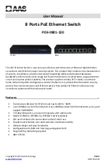
The D-Link DGS-1510-10L/ME is a high-performance, 10-port Gigabit Smart Managed Switch. For easy installation and setup, make sure to download the free Hardware Installation Manual from our website. This comprehensive manual provides step-by-step instructions and ensures a smooth setup process for your network. [website]
Page 1: ......
Page 3: ... FCC 21 CFR Chapter 1 Subchapter J in accordance with FDA CDRH requirements ...
Page 67: ......