D-Link DCS-9500T, Quick Installation Manual
The D-Link DCS-9500T offers exceptional performance and reliability. With its advanced features, it's essential to have a Quick Installation Manual to set it up effortlessly. Download the manual for free from manualshive.com to maximize your product's potential. Simplify your installation process with our comprehensive manual.
Share
Download


Reviews:
No comments
Related manuals for DCS-9500T

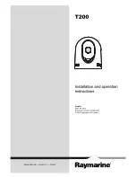
T300
Brand: Raymarine Pages: 38

DC-TH Series
Brand: Idis Pages: 14
DTI 1/19
Brand: Zeiss Pages: 88
HM-TD2H37T-10/X
Brand: Hikmicro Pages: 9

TCX series
Brand: FLIR Pages: 150

C.A 1879
Brand: Chauvin Arnoux Pages: 22
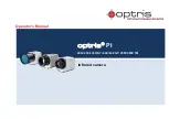
PI 640
Brand: optris Pages: 92

HM-TS03-15XF
Brand: Hikmicro Pages: 159
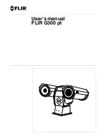
G300 pt Series
Brand: FLIR Pages: 80

testo 868s
Brand: ICS Schneider Messtechnik Pages: 42

Eagle Attack
Brand: Scott Pages: 36
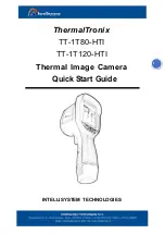
ThermalTronix TT-1T80-HTI
Brand: Intellisystem Pages: 5
E70110
Brand: Raymarine Pages: 47

THT500 Series
Brand: HT Pages: 54

TE-SQ1
Brand: i3system Pages: 8

ThermaCAM PM575
Brand: FLIR Pages: 68

FLIR Ex Series
Brand: DATATEC Pages: 41

MD 9910
Brand: METREL Pages: 17


