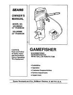
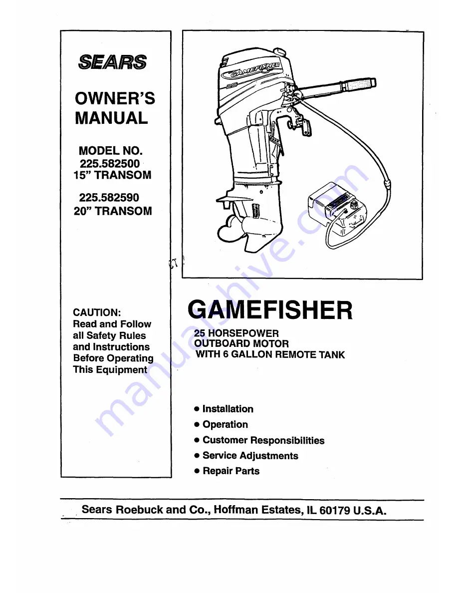
background image

Summary of Contents for GAMEFISHER 225.582500

Page 1: ... Read and Follow all Safety Rules and Instructions Before Operating This Equipment GAMEFISHER 25 HORSEPOWER OUTBOARD MOTOR WITH 6 GALLON REMOTE TANK Installation Operation Customer Responsibilities Service Adjustments Repair Parts Sears Roebuck and Co Hoffman Estates IL 60179 U S A ...

Page 2: ...ety labels posted on the outboard use safety alerts to draw your attention to special safety instructions that should be fol lowed Safety and operating information that is practiced along with using good common sense can help prevent personal injury and product damage ALWAYS DISCONNECT SPARK PLUG WIRES AND PLACE WIRES WHERE THEY CANNOT CONTACT SPARK PLUGS TO PREVENT ACCIDENTAL STARTING WHEN WORKIN...

Page 3: ...ATOR WHEN ATTACHED TO THE LANYARD MOVES FAR ENOUGH AWAY FROM THE OPERATOR S POSITION TO ACTIVATE THE SWITCH THIS WOULD OCCUR IF THE OPERATOR FALLS OR MOVES WITHIN THE BOAT A SUFFICIENT DIS TANCE FROM THE OPERATOR S POSITION THIS TYPE OF ACCIDENT IS MOST LIKELY IN CERTAIN TYPES OF BOATS SUCH AS LOW SIDED BASS BOATS HIGH PERFORMANCE BOATS AND LIGHT SENSITIVE HANDLING FISHING BOATS OPERATED BY HAND T...

Page 4: ...ine Drive Standard 10 3 8 Dia x 13 Pitch Spark Plug 33 811 Champion L82C Spark Plug Gap 035 in Fuel Tank Remote 6 0 gal 23 L Gear Ratio 2 25 1 No of Teeth Pinion Gear 12 Forward Reverse Gear 27 Weight approx 15 Leg 921bs 20 Leg 951bs Gasoline Oil Ratio 25 1 Break in 50 1 Normal CUSTOMER RESPONSIBILITIES Read and observe the safety rules Follow a regular schedule in maintaining caring for and using...

Page 5: ...p Filter 20 Fuel System Connection 15 Fuel Tank Filter 20 G Gasoline Selection 14 Gasoline Oil Break In Mixture 14 Gasoline Oil Mixing Ratio Chart 14 General Recommendations 18 I Index 5 Install Motor Cover 20 L Lubrication 19 M Maintenance Schedule 18 Motor Nomenclature 8 Motor lilt 10 Motor liltAngle 12 Mounting Motor 7 O Oil Recommendation 14 Operating Checks 13 Operating In Freezing Temperatur...

Page 6: ...OF DIA PITCH BLADES IN IN 3 10 3 8 13 3 10 114 14 1 2 3 10 3 8 11 3 10 3 8 9 112 2 10 3 8 13 MATERIAL Aluminum Aluminum Aluminum Aluminum Stainless Steel PART NO 48 19640A40 48 19642A40 48 19638A40 48 19636A10 48 19644A5 I I REMOVING MOTOR FROM CARTON TOOLS REQUIRED Utility Knife REMOVAL INSTRUCTIONS Cut along dotted lines A on top portion of carton being careful not to cut too deep and damage mot...

Page 7: ...WILL TEND TO CAUSE THE BOAT TO RUN OFF COURSE AND CREATE HARD STEER ING AND CONTROL 13ghten stem bracket clamp screws D alter nately by hand until tight Figure 2 IMPORTANT DO NOT USE WRENCH TO TIGHT EN CLAMP SCREWS FOR PERMANENT INSTALLATION OF ENGINE ON BOAT Drill two 1 4 in holes through the transom using stem bracket holes as a template Fasten with two bolts A flat washers B and Iocknuts 3 supp...

Page 8: ...Starter Rope Handle D Anti Cavitation Plate E Propeller F Skeg G Cooling Water Inlet H Gear Housing I Stem Brackets J Tiller Arm K Decal How to start L Warm Up Knob Richens the fuel air mixture when starting a cold engine M Stop Button Used to stop the engine N Shallow Water Drive Bar Allows operating at low speeds in shallow water at partial motor tilt O Transom Angle Pin Changes the motor to tra...

Page 9: ...h speed lockout to prevent high engine speeds until the shifter is moved to Forward or Reverse SHIFT CONTROL FIG 3 Shift only when engine is running Move shift lever E all the way to the right for For ward gear operation and all the way to the left for Reverse gear operation Shift into gear with a firm motion NEVER ease into gear TILLER ARM STORE POSITION FIG 4 5 Tiller arm A will tilt up or down ...

Page 10: ...re 6 C D Figure 7 III CO PILOT ADJUSTMENT IS NOT INTENDED TO ALLOW HANDS OFF STEERING LOSS OF CONTROL AND SERIOUS INJURY COULD OCCUR CO PILOT ADJUSTMENT FIG 8 Yourmotorhas an adjustable steeringfriction fea ture to allowyou to adjust the effortnecessary to steer _it motor up and lock in position Adjust screw A for steering friction desired Figure 8 SHALLOW WATER OPERATION FIG 9 The shallow water d...

Page 11: ...steering torque if the outboard is installed with the anti ventilation plate approximately 2 inches 50mm or more above the boat transom Operate your boat at normal cruisingspeed with the outboard set at the desired transom angle adjust ment Tum your boat left and rightand note the direc tion the boat tums more easily If adjustment is necessary loosen trim tab bolt and make small adjustments at a t...

Page 12: ...LOSE TO TRANSOM I BOW WILL DIG IN OR PLOW L_J TRANSOM ANGLE PIN TOO LOW MOTOR TOO CLOSE NORMAL YOUR MOTOR SHOULD REMAIN VERTICAL L CORRECT TRANSOM ANGLE PIN TOO HIGH MOTOR TOO FAR OUT ADJUST MOTOR ANGLE IF MOTOR IS TOO FAR AWAY FROM TRANSOM THE BOW MAY RIDE HIGH THE BOAT MAY uPORPOISE AND THE MOTOR MAY RACE Figure 10 Adjust motor angle if motor is too close to transom or bow it will dig in or plow...

Page 13: ...ers divers swimmers etc _ Boat is loaded evenly from front to rear _1 Operator has read and understood the entire owner s manual Check tightness of stem bracket clamp screws A Figure 11 IMPORTANT NEVER RUN MOTOR OUT OF WA TER AND NEVER RUN MOTOR UNLESS WATER PUMP IS WORKING NORMALLY OR OVERHEAT ING AND MOTOR DAMAGE MAY RESULT OPERATING CHECKS 1 Operator has carried out pre operation checklist 2 Ch...

Page 14: ...el system visually checking for leaks or abnormalities stabilizer container Run engine at least 5 minutes af ter adding stabilizer to allow the stabilizer to reach the carburetor You do not have to drain the fuel tank for storage if you are using fuel stabilizer OIL RECOMMENDATION Use SEARS ULTRA PREMIUM Certified TC W3 2 Cycle Outboard Oil Sears Ultra Premium Certified TC W3 Outboard Oil is a hig...

Page 15: ...r on fitting and release sleeve to lock in place F Figure 12 TO STOP Rotate Throttle Twist Grip C to Slow position shift engine A into Neutral Depress Stop button E Figure 13 and hold in until motor stops completely D F1 C E H Figure 13 EMERGENCY STOPPING A lanyard stop switch F2 is used to tum off the engine ignition whenever the operator when at tached to the lanyard F1 moves far enough away fro...

Page 16: ...ximately 112 throttle for ten minutes Check operation of the water pump and cooling system Refer to Checking Water Pump Operation Advance to full throttle for a few seconds Return to moderate speed for several minutes Repeat previous steps gradually increasing time of full throttle operation until 5 minutes of full throttle operation has been reached This break in operation will require approximat...

Page 17: ...THAT MAY HAVE ENTERED THE EXHAUST OUTLET IN THE GEAR CASE COULD FREEZE AND CAUSE DAM AGE TO THE OUTBOARD IMPORTANT IF THE MOTOR IS TILTED OUT OF THE WATER WATER REMAINING IN THE COOL ING SYSTEM AND GEAR HOUSING MAY FREEZE AND CAUSE PARTS TO BREAK Do not start a motor that might be frozen AND CHECK Figure 15 SALT WATER OPERATION Although all motor parts that contact water have been chemically treat...

Page 18: ... To receive full value from the warranty opera tor must maintain the outboard as instructed in this manual Some adjustments will need to be made periodically to properly maintain your unit All adjustments in the Service and Adjustments sec tion of this manual should be checked at least once each season As needed but at least annually you should re place the spark plugs fuel filters and water pump ...

Page 19: ...BRACKET GREASEFITTINGS PROPELMERSHAFT FIGURE 22 GEARHOUSING LUBRICATION CODE A Sears Outboard Gear Lube If not available use non corrosive EP 90 outboard gear lube B Waterproof Marine Grease All Purpose Auto Chassis Lubricant or Rykon 2 For temporary lubrication when above lubricants are not available use SAE 40 motor oil C Anti Seize Lubricant 19 ...

Page 20: ...tlyover seal Push down and tum release lever B to lockcowl in place A REMOVAL B I NSTALLATIO N A Figure 16 AVOID SPILLING FUEL AND KEEP ALL SOURCES OF HEAT FLAME AND SPARKS AWAY WHEN DISCONNECTING HANDLING OR STORING FUEL SYSTEM COMPONENTS CHECK REPLACE FUEL LINE FILTER FIG 17 Remove motor cowl Inspect fuel linefilter A If the filter appears con taminated remove and replace the filter A Figure17 C...

Page 21: ... to 20 lb ft 27 N m CHECK ENGINE COOLING SYSTEM If the motor overheats check that a spray of water is coming out of the water pump indicator hose Figure 19 If no water is present stop motor IM MEDIATELY and have your Sears Service Center check for cause A Figure 19 SHIFT INTO NEUTRAL GEAR POSITION AND DISCONNECT SPARK PLUG WIRES TO PREVENT ACCIDENTAL STARTING AND SERIOUS INJURY WHILE SERVICING THE...

Page 22: ...oded Never paint or apply a protectivecoating on the anode as thiswill re duce effectiveness of the anode A B Figure 23 ADDING REFILLING LUBRICANT Remove fill and drain screw and washer and in sert nozzle of tube into hole Remove vent screw and washer Add lube until it appears at vent hole Reinstall vent screw and washer Tighten secure ly Remove nozzle reinstall fill and drain screw and washer Tig...

Page 23: ...dle adjustment needle in clockwise until it seats lightly Figure 24 Back needle out one and one half 1 1 2 full turns FINAL ADJUSTMENT IMPORTANT DO NOT ADJUST LEANER THAN NECESSARY TO OBTAIN SMOOTH IDLING IT IS BE n ER TO HAVE IDLE SET A LITTLE RICH THAN TOO LEAN A LEAN SETTING CAN CAUSE MO TOR DAMAGE With boat tied securely to dock start motor and run until fully warmed up Set controls to lowest ...

Page 24: ...ile in storage To avoid engine problems the fuel system should be emptied before storage of 30 days or longer Follow these instructions Maintain motor in an upright position until all cool ing water is drained out I Figure 25 Figure 26 Drain and refill gear housing as outlined in Lubrication Lubricate and service propeller as outlined in Maintenance Remove spark plugs put an ounce or two of out bo...

Page 25: ...nformation They can also perform maintenance as required bywarranty test run yourmotor and performtune up and adjustments needed for good operation If your motor cannot be returned to your Sears Service Center do the following steps Remove spark plugsand clean or replace as out lined under Maintenance Lubricate all parts as outlined under Lubrication Check lubricant in gear housing as outlined un ...

Page 26: ...s Dirty or Clogged Motor Flooded Vent Screw on Fuel Tank Filler Cap Closed Air Leak in Motor Air Leak in Fuel System Carburetor Passages Clogged or Dirty 0 Incorrect Fuel_Oil Mixlure Carburetor Out of Adjustment Wrong Type Spark Plugs o Defective or Fouled Spark Plugs Weak Ignition Coil i Spark Plug Lead Wires Switched Frayed or Cracked Lead Wire Insulation Disconnected Grounded or Loose Wiring 26...

Page 27: ...P BRACKETS 50 GEAR HOUSING DRIVESHAFT 52 GEAR HOUSING PROPELLER SHAFT 54 FUEL TANK AND LINE ASSEMBLY 56 MISCELLANEOUS PARTS 57 OPT Optional AR As Required NSS Not Sold Seperate NS Not Shown NOTE All part numbers preceded by a e are new and listed for the first time NOTE Indented description indicate that these parts are included in preceding assembly THESE PARTS BOOKS FICHE CARDS ARE COPYRIGHTED A...

Page 28: ...COWL ASSEMBLY TOP AND BOTTOM GAMEFISHER 25 H P MODELS 225 582500 15 TRANSOM and 225 582590 20 TRANSOM 12A SIDE STARBOARD SIDE 12 i 6 7 I 5 3 _2 25 OWNERS MANUAL PARTS CATALOG 18 28 15 ...

Page 29: ...2 71055 13 26992 10 28635 93527 1 90 830212 2 QUAN 1 1 1 1 1 7 7 7 1 1 1 2 1 1 1 1 1 1 1 1 1 2 1 1 1 1 1 1 1 DESCRIPTION COWL ASSEMBLY Top Painted With Decals COWL ASSEMBLY Top Painted Without Decals BAFFLE BRACKET Front RETAINER Rear Cowl SCREW M4 x 14 5 LOCKWASHER 8 NUT a4 ROLLER Latch SCREW Latch Roller NUT 1 4 20 WASHER DECAL Starboard DECAL Port DECAL Rear DECAL Front Starting Instructions PA...

Page 30: ...IGNITION SYSTEM GAMEFISHER 25 H P MODELS 225 582500 15 TRANSOM and 225 582590 20 TRANSOM 8 Q_ 24 15 30 ...

Page 31: ... 3 OPT 1 AR AR 1 1 DESCRIPTION STATOR ASSEMBLY COMPLETE PLATE Stator MODULE KIT Ignition With Splice Kit BOOT KIT Spark Plug SCREW 8 32 x 3 4 Ignition Module Mount CABLE KIT Modules To Harness SPLICE KIT Ignition Module Wire MARKER SET Ignition Cables 1 2 3 NUT Flywheel FLYWHEEL Painted SWITCH ASSEMBLY Stop COVER ASSEMBLY Stop Switch BEZEL Stop Switch Cover SWITCH ASSEMBLY Emergency Stop NUT Stop ...

Page 32: ...SHIFT LINKAGE GAMEFISHER 25 H P MODELS 225 582500 15 TRANSOM and 225 582590 20 TRANSOM 12 I 20 26 _ 27 31 ____ 33 32 ...

Page 33: ... 1 1 1 1 1 2 1 1 1 1 1 1 1 2 1 1 1 1 1 1 1 DESCRIPTION STOP Starter Pulley Interlock ARM Starter Interlock WASHER SCREW 10 16 x 112 LINK Interlock LEVER Intermediate Interlock NUT 10 32 SPRING Interlock Lever STUD Interlock Lever BEARING Spark Control STUD 1 4 20 x 1 69 LEVER Neutral Speed Interlock NUT 1 4 20 ROD Interlock SCREW Shoulder CONNECTOR Gear Shift Rod STUD End Connector LOCKWASHER 10 I...

Page 34: ...FUEL SYSTEM GAMEFISHER 25 H P MODELS 225 582500 15 TRANSOM and 225 582590 20 TRANSOM TO CARB 14 f 5 13 8 TO GARB ELBOW 34 ...

Page 35: ... F681046 32 819398 53 35 816296 22 F197767 2 QUAN 1 1 2 2 2 1A AR 1 1 1 1 1 1 1 1 DESCRIPTION PUMP ASSEMBLY Fuel GASKET DIAPHRAGM KIT WASHER Not Sold Seperate SCREW 10 24 x 1 1 4 SCREW 10 24 x 1 5 8 O RING CABLE TIE 4 HOSE 1 5 8 Cut as Req d HOSE 3 1 8 Cut as Req d HOSE 15 1 2 COVER Primer Bulb BULB Primer HOSE 11 1 2 Cut as Req d FILTER Fuel CONNECTOR Fuel Component of Powerhead Assy 800 819240A3...

Page 36: ...CARBURETOR GAMEFISHER 25 H P MODELS 225 582500 15 TRANSOM and 225 582590 20 TRANSOM 6 31 3O 38 3z_ _q5 35 34 4 _14 REPAIR KIT GASKET SET 36 ...

Page 37: ... 1 1 1 1 1 1 1 1 1 1 1 DESCRIPTION CARBURETOR FO JB PLUG Cup TUBE By Pass PLUG Welch SHUTTER Throttle SCREW Shutters E RING Throttle Linkage SPRING Choke Friction BALL NOZZLE Main PIN Float FLOAT Fuel Bowl GASKET Fuel Bowl GASKET Fuel Bowl BOWL Fuel SCREW Fuel Bowl JET Main 058 0 2500 JET Main 056 2500 5000 JET Main 054 5000 7500 JET Main 052 7500 10000 NEEDLE Inlet NOTE Do Not Remove Inlet Seat S...

Page 38: ...STARTER GAMEFISHER 25 H P MODELS 225 582500 15 TRANSOM and 225 582590 20 TRANSOM 38 ...

Page 39: ... 1 1 3 3 1 1 1A 1 3 1 1 1 1 1 3 3 2 1 1 1 2 1 1 DESCRIPTION HOUSING Starter DECAL KIT Shift to Neutral SCREW 1 4 20 x 3 4 INSERT Starter Housing INSERT Rope Starter Housing RING Retaining BRACKET Starter Housing Front Painted NUT 1 4 20 SCREW 1 4 20 x 5 8 SPRING Starter Rewind PULLEY ASSEMBLY Starter Rewind PLUG Pulley SEAL Pulley Bearing ROPE 64 67 RETAINER Starter Pulley SCREW 10 16 x 1 2 SCREW ...

Page 40: ...CRANKSHAFT AND PISTON GAMEFISHER 25 H P MODELS 225 582500 15 TRANSOM and 225 582590 20 TRANSOM 17 18 16 I 7 7 8 10 j15 19 40 ...

Page 41: ... 1 4A 4A 3A 6 72 6 3 1A 1A 3A 6 3 1 1 DESCRIPTION CAGE ASSEMBLY Crankshaft SEAL Oil SCREW 1 4 20 x 3 4 GASKET Crankshaft Beadng Cage CRANKSHAFT ASSEMBLY BEARING Ball LINER Center Main Rollers ROLLERS 16 Per Strip CONNECTING ROD ASSEMBLY SCREW Conn Rod NEEDLE BEARING BEARING Thrust BEARING KIT BEARING Crankshaft Lower Main SEAL Crankshaft Lower PISTON KIT STANDARD LOCK RING RING SET 2 Rings STANDAR...

Page 42: ...CYLINDER BLOCK GAMEFISHER 25 H R MODELS 225 582500 15 TRANSOM and 225 582590 20 TRANSOM 32 31 36 31 27 7 12 GASKET SET 15 _ 16 8 42 2 17 42 ...

Page 43: ...1 1 1 1 3 1 DESCRIPTION POWERHEAD ASSEMBLY Painted CYLINDER ASSEMBLY Painted SCREW 1 4 20 x 3 4 WASHER SCREW 5 16 18 x 1 WASHER PIN Dowel TUBE Water Jacket CHECK VALVE TUBING 2 Pcs 15 1 Pc 12 3 4 Cut as Req d STUD 5 16 24 x 1 1 4 STUD 1 4 20 x 1 69 With Dri Loc GASKET SET Contents of Gasket Set COVER Exhaust Painted SCREW 1 4 20 x 1 1 4 GASKET Exhaust Cover PLATE Exhaust SCREW 1 4 20 x 5 8 Ground ...

Page 44: ...REED PLATE GAMEFISHER 25 H P MODELS 225 582500 15 TRANSOM and 225 582590 20 TRANSOM 7 10 11 0 2 5 44 ...

Page 45: ...4 9 e27 819142 10 819153T 11 27 819141 QUAN 1A 2 2 2 7A 6A 6A 12A 1A 1A 1A DESCRIPTION MANIFOLD ASSEMBLY Intake CHECK VALVE STUD 1 4 20 x 91 With Dri Loc NUT 1 4 20 Carburetor Mount SCREW 1 4 20 x 1 1 4 REED STOP Reed SCREW WITH LOCKWASHER 6 32 x 5 16 GASKET Reed Plate PLATE Reed GASKET Intake Manifold Component of Powerhead Assy 800 819240A3 Contents of Powerhead Gasket Set 27 809516A1 45 ...

Page 46: ...TILLER HANDLE AND THROTTLE LINKAGE GAMEFISHER 25 H P MODELS 225 582500 15 TRANSOM and 225 582590 20 TRANSOM 5 6 20 3 36 O 35 23 25 26 27 46 ...

Page 47: ... 1 1 2 2 1 1 1 1 1 1 1 1 1 1 1 1A 1 1 SHAFT Magneto Control BUSHING RETAINER KIT Steering Shaft SCREW Set 1 4 28 x 1 4 PIN Roll GEAR Steering Shaft PIN Groove SCREW Pivot SPRING Steering Handle Stop BUSHING STOP Steering Handle ARM KINGPIN ASSEMBLY Steering Painted SCREW 1 4 20 x 1 3 4 BUMPER NUT 1 4 20 LOCKWASHER 5 16 Internal SCREW 5 16 18 x 1 1 8 INSERT Steering Handle Pivot BUSHING WASHER Stee...

Page 48: ...SWIVEL BRACKET AND DRIVESHAFT HOUSING GAMEFISHER 25 H P MODELS 225 582500 15 TRANSOM and 225 582590 20 TRANSOM 3_ 38 16 21 31 _o I 18 25 SeePage 46 47 I _ Ref No 12 26 b 48 ...

Page 49: ...4 1 1 1 1 1 1 2 DESCRIPTION WASH ER Swivel Bracket BRACKET KIT Swivel Painted BEARING 1 314 BEARING 1 118 FITTING Grease SHOE Friction CLAMP Steering Friction SCREW 1 4 20 x 1 3 8 WASHER NUT 1 4 20 PIN Spring PIN Spring BUSHING LEVER Reverse Lock LEVER ASSEMBLY Reverse Lock Intermediate BUSHING WASHER LEVER Reverse Lock Release PIN Groove WASHER Stern Bracket DECAL Fuel Mix DECAL Tilt Release LINK...

Page 50: ...CLAMP BRACKETS GAMEFISHER 25 H P MODELS 225 582500 15 TRANSOM and 225 582590 20 TRANSOM 25 24 3 4 6 50 ...

Page 51: ...F429541 24 23 819226 25 24 F286544 1 QUAN 2 1 2 2 2 2 1 2 2 2 2 2 1 1 1 1 1 1 2 1 2 1 1 1 1 DESCRIPTION BRACKET Stern Painted BOLT Pivot Stern Bracket SCREW 1 4 20 x 3 Mounting WASHER Thin Mounting WASHER Mounting NUT 1 4 20 Mounting HANDLE Carrying SCREW Stern Bracket PIN Roll HANDLE Clamp Screw Painted FOOT Stem Bracket Screw SCREW 10 32 x 1 2 BAR KIT Lock Stem Bracket PIN Roll SPRING Lock Bar H...

Page 52: ...GEAR HOUSING DRIVESHAFT GAMEFISHER 25 H P MODELS 225 582500 15 TRANSOM and 225 582590 20 TRANSOM 67 s WATER PUMP KIT 5 11 52 ...

Page 53: ... Painted GEAR HOUSING ASSY 20 COMPLETE Painted GEAR HOUSING ASSY BASIC Painted SLEEVE Included With Ref 1 SEAL Driveshaft BEARING Roller Upper PIN Dowel 187 x 53 SCREW KIT 3 8 16 x 25 Special WASHER Sealing SCREEN Water Inlet Port SCREW M5 x 40 PLUG KIT Drain Magnetic WASHER Sealing SCREEN Water Inlet Starboard NUT M5 Screen Screw BEARING ASSEMBLY Roller CUP Roller Bearing Included With Ref 13 SCR...

Page 54: ...GEAR HOUSING PROPELLER SHAFT GAMEFISHER 25 H P MODELS 225 582500 15 TRANSOM and 225 582590 20 TRANSOM GAI_ 65 45 61 60 59 58 57 SEAL KIT 56 WATER PUMP KIT 55 54 4 54 ...

Page 55: ...1 1 1 1 1 1 1 1 1 1 1D 1 1 4 4 1 1 1 1 1 1 1 1 1 DESCRIPTION GEAR HOUSING ASSY 15 COMPLE I _ Painted GEAR HOUSING ASSY 20 COMPLETE Painted GEAR HOUSING ASSY BASIC Painted TRIM TAB SCREW M8 x 30 WASHER WASHER SCREW M5 x 16 Special BEARING ASSEMBLY Roller CUP Roller Bearing GEAR ASSEMBLY Forward BUSHING FOLLOWER Cam SPRING CLUTCH PIN Cross SPRING PROPSHAFT GEAR Reverse CARRIER ASSEMBLY Bearing BEARI...

Page 56: ...FUEL TANK AND LINE ASSEMBLY 6 6 GALLON GAMEFISHER 25 H P MODELS 225 582500 15 TRANSOM and 225 582590 20 TRANSOM 11 8 10 15 _ 2 56 ...

Page 57: ...lter LINE ASSEMBLY Fuel 5 16 I D 30 60 BULB ASSEMBLY Primer VALVE Check INLET VALVE Check OUTLET CLAMP LARGE CLAMP SMALL CONNECTOR Fuel Engine SEAL SMALL SEAL LARGE CONNECTOR Fuel Tank CLAMP SMALL LINE Fuel 9 Cut as Req d LINE Fuel 100 Cut as Req d GAMEFISHER 25 H P MISCELLANEOUS PARTS MODELS 225 582500 15 TRANSOM and 225 582590 20 TRANSOM REF NO D B m o m PART NO 92 818252 12 F5S211 2 92 825321 1...

Page 58: ...ched to the port stem bracket All parts listed herein may be ordered through Sears Roe buck and Co Service Centers and most Retail Stores WHEN ORDERING REPAIR PARTS ALWAYS GIVE THE FOLLOWING INFORMATION PRODUCT OUTBOARD MOTOR 225 582500 15 TRANSOM MODEL NUMBER 225 582590 20 TRANSOM SERIAL NUMBER PART NUMBER PART DESCRIPTION Your Sears merchandise has added value when you con sider that Sears has s...

Reviews: