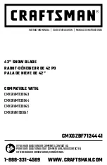
background image

42" SNOW BLADE

RABOT-DÉNEIGEUR DE 42 PO 

PALA DE NIEVE DE 42”

CMXGZBF7124441

If you have questIons or comments, contact us.

Pour toute questIon ou tout commentaIre, nous contacter.

sI tIene dudas o comentarIos, contáctenos.

1-888-331-4569      WWW.CRAFTSMAN.COM

InstructIon Manual   |   GuIde d’utIlIsatIon   |   Manual de InstructIones
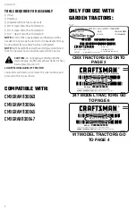
COMPATIBLE WITh:

cmXGram1130043
cmXGram1130044
cmXGram1130045
cmXGran1130047

Summary of Contents for CMXGZBF7124441

Page 1: ...equestionsorcomments contactus Pourtoutequestionoutoutcommentaire nouscontacter Sitienedudasocomentarios contáctenos 1 888 331 4569 www craftsman com InstructionManual GuideD utilisation Manualdeinstructiones Compatible with CMXGRAM1130043 CMXGRAM1130044 CMXGRAM1130045 CMXGRAN1130047 ...

Page 2: ... injury Caution Indicates a potentially hazardous situation which if not avoided may result in minor or moderate injury Used without word Indicates a safety related message Notice Indicates a practice not related to personal injury which if not avoided may result in property damage Safety Warnings WARNING Read all safety warnings instructions illustrations and specifications provided with this too...

Page 3: ... 47810 HA21362 R19172410 43055 Z 2 43407 43070 43081 R19171616 43010 R 6 43003 44917 23658 46053 19 22 20 14 13 16 15 17 23 25 24 18 21 For model 917 tractors 26 27611 27612 48167 25647 24023 63033 24520 49808 27864 For model CMX 247 tractors HARDWARE PACKAGE CONTENTS 1 2 2 1 3 4 2 5 1 6 1 7 1 10 2 8 1 9 1 11 1 12 2 45700 05762 43348 726 0178 23856 46065 731 0869 62561 23151 24690 46066 ...

Page 4: ...gin assembling until the tractor engine muffler and exhaust deflector have been allowed to cool off LOCATE MODEL LABEL OF TRACTOR Look under your tractor seat locate the serial number and proceed to the step as shown Compatible with CMXGRAM1130043 CMXGRAM1130044 CMXGRAM1130045 CMXGRAN1130047 Fig 3 193653 MODEL 917 000000 SERIAL 000000A000000 193653 MODEL 247 000000 SERIAL 000000A000000 MODEL NUMBE...

Page 5: ...ts to the quick attach brackets 3 Tighten the 4 bolts fastening the pivot support bracket to the slotted angle support brackets 4 GOTO PAGE 7 3 8 x 1 HEX BOLT D 3 8 NYLOCK NUT M PIVOT SUPPORT BRACKET Fig 2 Step 3 Fig 3 1 Assemble a shoulder bolt I and a 3 8 nylock nut M to the front of the tractor frame on each side unless a shoulder bolt is already present SHOULDER BOLT I 3 8 NYLOCK NUT M 3 8 x 3...

Page 6: ...n in figure 8 2 If your tractor resembles the top illustration go to page 5 figure 9 3 If your tractor resembles the bottom illustration go to page 5 figure 11 FRONT SUSPENSION BRACKET TYPE A FRONT SUSPENSION BRACKET TYPE B Fig 8 INSTRUCTIONS FOR 917 MODEL TRACTORS Step 1 Fig 5 LOCATE THE MOWER SUSPENSION BRACKETS 1 If there is a single mower deck suspension bracket underneath the middle of the fr...

Page 7: ...R H HANGER BRACKET Fig 10 INSTRUCTIONS FOR TYPE B TRACTORS Step 1 Fig 11 1 Remove any bolts found in the holes indicated in the illustration REMOVE BOLTS FROM THESE HOLES FRONT SUSPENSION BRACKET Fig 11 Step 2 Fig 12 1 Attach the R H hanger bracket to the three holes shown on the side of the tractor frame using three 3 8 x 1 hex bolts D 3 8 lock washers R 3 8 flat washers O and 1 2 large washers N...

Page 8: ...ort bracket to the angle support brackets 4 GO TO PAGE 7 FIGURE 19 PIVOT SUPPORT BRACKET 3 8 NYLOCK NUT M 3 8 x 1 HEX BOLT D Fig 13 Fig 14 INSTRUCTIONS FOR 247 MODEL TRACTORS Step 1 Fig 15 1 Attach an angle support bracket 23 to the top holes in the quick attach brackets using two 3 8 x 1 hex bolts D and 3 8 nylock nuts M Do not tighten 2 Attach an angle support bracket to the bottom holes in the ...

Page 9: ... x 1 1 4 carriage bolt E and one 3 8 nylock nut M Be sure to insert bolt from side indicated Do not tighten 2 Hold the angle lock bars so that the square holes are at the top Insert the straight hook end of the angle lock spring through the middle hole in both angle lock bars 3 8 x 1 1 4 CARRIAGE BOLT E 3 8 NYLOCK NUT M ANGLE LOCK BARS 10 ANGLE LOCK SPRING 3 Step 4 Fig 18 1 Pull out on the attachm...

Page 10: ...les Support the assembled end of the spring mount rod on a block of wood and assemble the remaining palnut onto the other end of the rod 3 8 PALNUT S PIVOT PLATE SPRING MOUNT ROD 5 3 8 PALNUT S Fig 21 Step 4 Fig 22 1 Assemble a 3 8 x 1 1 4 carriage bolt E through the square hole in the Cable Mount Bracket and through the square hole in the angle lock bars The carriage bolts should face in opposite...

Page 11: ...vot plate with the notched holes in the blade Insert a 1 8 x 1 1 4 cotter pin V down through the hole at the bend in the blade pivot shaft Spread the ends of the pin From the left side insert the blade pivot shaft bend facing top of blade through the notched holes Secure the shaft with another 1 8 x 1 1 4 cotter pin V through the end hole in the shaft Spread the ends of the pin 2 Remove the plasti...

Page 12: ...BRACKET LIFT HANDLE TUBE 20 Fig 27 Step 10 Fig 28 1 Remove the rubber cap and the first jam nut from the threaded end of the control cable and slide them onto the control cable wire Adjust the second jam nut on the threads so that it is approximately 3 4 from end Assemble threaded end of cable through the cable mount bracket Mount the bracket and secure it with the first jam nut Reinstall the rubb...

Page 13: ...embly to check blade pivot To adjust see Service Adjustments section on page 14 BLADE PIVOT ROD 19 LIFT HANDLE TUBE BLADE PIVOT SHAFT HAIRPIN COTTER W HAIRPIN COTTER W PLASTIC TIES 4 Fig 30 Step 13 Fig 31 1 Pivot the blade to the center position and lower it to the ground Place shims under the blade to create the amount of ground clearance you want The more uneven the surface the more clearance yo...

Page 14: ...ed before operating the Snow Blade Avoid pipes roots curbs or other heavy obstructions CAUTION Always lower the blade to the gorund before leaving the tractor CAUTION Know the terrain Avoid exceptionally steep slopes or drop offs which may be hidden by the snow Never run the Snow Blade into heavy material at high speed BLADE SHOE BLADE PIVOT SHAFT LIFT HANDLE TUBE BLADE PIVOT ROD BLADE ADJUST SPRI...

Page 15: ...Service Dates E v e r y s e a s o n B e f o r e s t o r a g e Check for loose fasteners X Check for worn or damaged parts X Clean Blade X X Lubricate Blade X MAINTENANCE Read and follow the maintenance schedule and the procedures listed in the maintenance schedule Customer Responsibilities Check for Loose Fasteners During the operating season check all Bolts Nuts and Hairpin Cotters to be sure the...

Page 16: ...and touch up with paint Touch up bare metal with paint or apply a light coat of grease or rust preventative Lubricate all pivot points and all points shown in Figure 34 of the Maintanence section Store in a dry area protected from weather To Remove Blade from Tractor Lower the blade to the ground with the Blade in the center Straight Ahead position Remove the Hairpin Cotter which fastens the Blade...

Page 17: ...eplacement If your warning labels become illegible or are missing call 1 888 331 4569 for a free replacement CRAFTSMAN is a registered trademark of Stanley Black Decker Inc used under license es una marca registrada de Stanley Black Decker Inc utilizada bajo licencia est une marque déposée de Stanley Black Decker Inc utilisée sous licence 2018 CRAFTSMAN U S Canada Only É U et Canada seulement Made...

Page 18: ...er l assemblage tant que le moteur du tracteur le silencieux et le déflecteur d échappement n ont pas refroidi LOCALISATION DE L ÉTIQUETTE DE MODÈLE DU TRACTEUR Regarder sous le siège du tracteur localiser le numéro de série et poursuivre comme indiqué ci dessous Utiliser exclusivement avec des tracteurs de jardin INSTRUCTIONS POUR LES TRACTEURS MODÈLE CMX Étape 1 Fig 1 1 Fixer une équerre de fixa...

Page 19: ...e retrait du second boulon pour l empêcher de tomber REMARQUE Réinstaller l écran anti brunissement avant d utiliser le tracteur INSTRUCTIONS POUR LES TRACTEURS AVEC DEUX SUPPORTS DE SUSPENSION DE PLATEFORME AVANT Étape 1 Fig 8 1 Comparer le tracteur utilisé à ceux illustrés à la figure 8 2 S il ressemble à l illustration du haut aller à la figure 9 3 S il ressemble à l illustration du bas aller à...

Page 20: ...ner l illustration ci dessous qui ressemble le plus à votre tracteur 2 Monter un boulon à épaulement I et un écrou nyloc de 9 5 mm M sur l avant du châssis du tracteur de chaque côté sauf si un boulon à épaulement est déjà présent Étape 4 Fig 18 1 Sortir les goupilles de fixation de l attelage et écarter le haut des goupilles des trous dans lesquels elles se trouvaient en les basculant 2 Accrocher...

Page 21: ...mités de la goupille En partant de la gauche insérer l arbre du pivot du rabot déneigeur le coude tourné vers le haut du rabot déneigeur dans les trous crantés Fixer l arbre en enfilant une autre goupille fendue de 3 mm x 31 7 mm V dans le trou à l extrémité de l arbre Écarter les extrémités de la goupille 2 Enlever le capuchon en plastique et un écrou hexagonal de 9 5 mm du boulon dans le ressort...

Page 22: ... mm L Serrer les boulons avec les sabots de patin en appui au sol FONCTIONNEMENT Lire le présent manuel du propriétaire et les consignes de sécurité avant d utiliser le rabot déneigeur Utiliser l illustration ci dessous du rabot déneigeur pour se familiariser avec ses différentes commandes et leur emplacement Explication des pièces Poignée de verrouillage déverrouillage déverrouille le rabot dénei...

Page 23: ...age de tous les boulons écrous et goupilles fendues Vérifier les pièces usées ou endommagées durant la saison d utilisation nettoyer le rabot déneigeur après chaque utilisation Retoucher tout métal nu avec de la peinture ou appliquer une fine pellicule de graisse ou d antirouille Lubrifier le rabot déneigeur Fig 34 Lubricate all Pivot points to help maintain proper operation of Blade Apply a light...

Page 24: ...ur au sol en position centrale droit devant Enlever la goupille fendue qui fixe la tige du pivot du rabot déneigeur sur l arbre du pivot du rabot déneigeur Voir la figure 30 Enlever la goupille fendue qui fixe la tige de la poignée de levage sur la goupille du bras de levage Voir la figure 27 Enlever la goupille fendue du tourillon du canal et enlever le tourillon du canal Voir la figure 26 Enleve...

Page 25: ...continúe con el paso siguiente que se muestra Solo para uso con tractores de jardín INSTRUCCIONES PARA TRACTORES DE MODELO CMX Paso 1 Fig 1 1 Fije un soporte angular a los orificios superiores de los soportes de fijación rápida con dos pernos hexagonales de 3 8 x 1 D y tuercas mecánicas con brida de 3 8 Y No ajuste 2 Fije un soporte angular a los orificios inferiores de los soportes de fijación rá...

Page 26: ...ere ver las instrucciones para quitar el capó correctamente 2 Quite el protector inferior de la parte delantera del tractor como se muestra Sostenga el protector mientras quita el segundo perno para evitar que se caiga NOTA Vuelva a instalar el protector inferior antes de usar el tractor INSTRUCCIONES PARA TRACTORES CON SOPORTES DE SUSPENSIÓN DELANTERA DE PLATAFORMA DOBLES Paso 1 Fig 8 1 Compare s...

Page 27: ... tuerca mecánica de seguridad de 3 8 M en la parte delantera de cada lado del bastidor del tractor a menos que ya haya un perno de tope instalado Paso 4 Fig 18 1 Retire los pasadores de sujeción del conjunto de acople y gire la parte superior de los pasadores hacia abajo en dirección opuesta a los orificios en los que estaban insertados 2 Enganche el conjunto de acople en los pernos de tope que es...

Page 28: ...control a través del orificio en la conexión del extremo del cable y tire hasta que la bola se deslice dentro el borde ondulado de la conexión Si la bola no se desliza debajo del borde de la ondulación se deberá insertar a través del extremo abierto 2 Instale un perno hexagonal de 1 4 x 1 1 2 B a través de la conexión del extremo del cable el espaciador largo de 5 8 T y el orificio izquierdo en el...

Page 29: ...levación con un perno hexagonal de 5 16 x 1 1 2 C y una tuerca mecánica de seguridad de 5 16 L No ajuste demasiado la tuerca mecánica de seguridad El conjunto del mango debe pivotar libremente 3 Monte el extremo de bola del cable a una conexión del extremo del cable como lo hizo en el otro extremo Asegure la conexión del extremo del cable al perno soldado en el mango de desbloqueo con una tuerca m...

Page 30: ...de la manivela Para elevar la pala tire hacia atrás mientras presiona el mango de la manivela hacia abajo Para bajar la pala tire hacia atrás mientras levanta el mango de la manivela Para pivotar la pala Fig 33 Eleve la pala hasta la posición de transporte Para desbloquear la pala presione el mango de desbloqueo hacia abajo contra el tubo de la manivela Para pivotar la pala mantenga el mango presi...

Page 31: ...ranuras en la placa pivotante ALMACENAMIENTO Recomendaciones para el almacenamiento Cuando no se use la pala de nieve elimine toda la suciedad y el óxido y aplique una capa de pintura Pinte las piezas que tengan el metal expuesto o bien aplique una ligera capa de grasa o antioxidante Lubrique todos los puntos pivotantes y todos los puntos que se muestran en la Figura 34 de la sección Mantenimiento...

Page 32: ... 32 42 56 15 14 19 39 40 24 27 20 48 48 37 47 41 41 25 36 25 61 69 68 70 63 62 65 60 16 64 66 25 11 36 21 17 13 44 47 43 12 26 4 5 4 7 7 44 44 44 44 47 31 55 36 25 C C 57 54 2 1 9 18 22 29 28 49 51 9 51 51 51 59 51 16 16 44 16 16 16 16 16 5 52 58 52 53 38 58 67 OPTIONAL ACCESSORY ...

Page 33: ...34 23856 1 Spring Mount Rod 35 44917 2 Palnut 3 8 36 43010 3 Cotter Pin 1 8 x 1 1 4 ref part no qty description 37 43348 1 Angle Lock Spring 38 746 0260 2 Cable End Fitting 39 731 0869 1 Grip Plastic 40 46471 1 Handle Grip 41 712 0256 2 Hex Jam Nut 5 16 24 Thread 42 23658 1 Spacer 43 43085 1 Hex Bolt 5 16 18 x 1 1 2 44 47810 13 Nylock Hex Nut 5 16 45 05762 1 Cable Mount Bracket 46 43648 1 Hex Bolt...

Page 34: ......

Page 35: ......

Page 36: ...strada de Stanley Black Decker Inc utilizada bajo licencia est une marque déposée de Stanley Black Decker Inc utilisée sous licence 2018 CRAFTSMAN Product Manufactured by Producto fabricado por Produit fabriqué par Agri Fab Inc 809 South Hamilton Street Sullivan Illinois 61951 USA U S Canada Only É U et Canada seulement ...

Reviews: