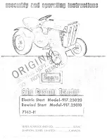
Craftsman 917.25010 Assembly and, Assembly And Operating Instructions Manual
The Craftsman 917.25010 Assembly and Operating Instructions Manual is a comprehensive guide that provides step-by-step instructions on how to assemble and operate this exceptional product. Available for free download at manualshive.com, this manual ensures you have everything you need for a successful setup and efficient usage experience.
Share
Download


Reviews:
No comments
Related manuals for 917.25010 Assembly and
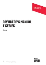
T Series
Brand: Valtra Pages: 31
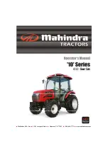
10 Series
Brand: Mahindra Pages: 120
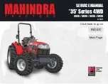
35 Series
Brand: Mahindra Pages: 368
600
Brand: Valtra Pages: 142
770
Brand: David Brown Pages: 93

2810
Brand: Mahindra Pages: 223
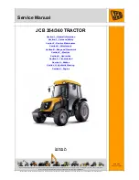
354
Brand: jcb Pages: 21

1149MT
Brand: FENDT Pages: 31

G-10
Brand: Jacobsen Pages: 54
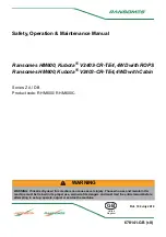
HM600
Brand: Ransomes Pages: 134

MB7000
Brand: Nakayama Pages: 24
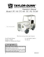
TC-30
Brand: Taylor-Dunn Pages: 60
5860
Brand: LANDINI Pages: 132

MAJOR
Brand: Zetor Pages: 108

4160
Brand: jcb Pages: 31

4400 BROCHURE 74-101
Brand: MASSEY FERGUSON Pages: 20
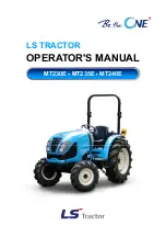
MT230E 2020
Brand: LS tractor Pages: 218

KIOTI PX1053
Brand: Daedong Pages: 256


