

00011
Important:
Read and fol low
all Safety Rules
and In struc tions
Be fore Op er at ing
This Equip ment
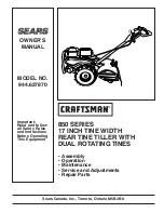
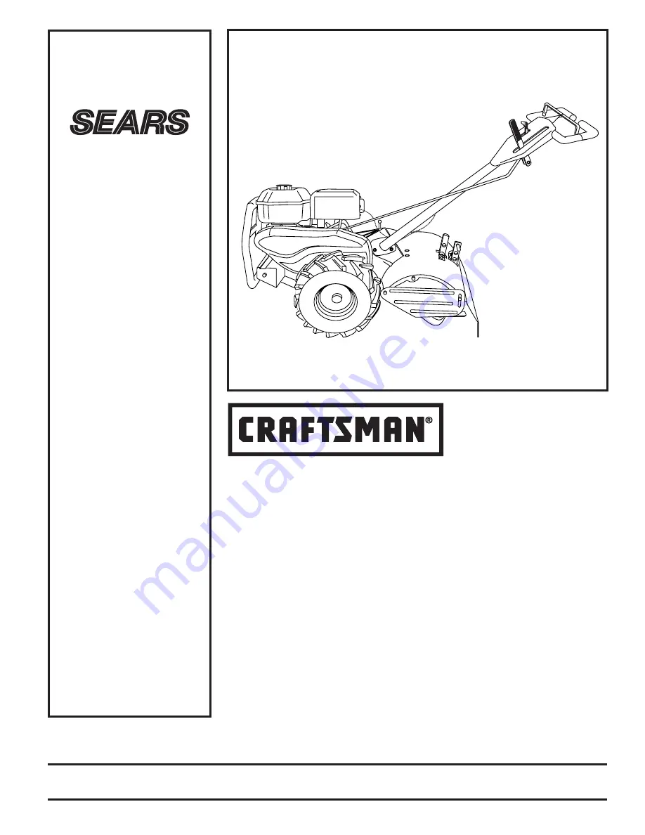
MODEL NO.
944.627870
OWNER’S
MANUAL
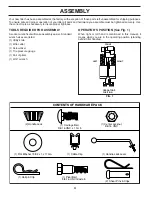
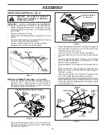
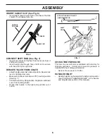
• Assembly
• Operation
• Maintenance
• Service and Ad just ments
• Repair Parts
850 SERIES
17 INCH TINE WIDTH
REAR TINE TILLER WITH
DUAL ROTATING TINES
Sears Canada, Inc., Toronto, Ontario M5B 2B8
Summary of Contents for 850 Series
Page 33: ...33 SERVICE NOTES ...
Page 34: ...34 SERVICE NOTES ...
Page 35: ...35 SERVICE NOTES ...
Page 36: ...PRINTED IN THE U S A 411772 02 02 07 CL 02488 ...


