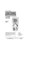
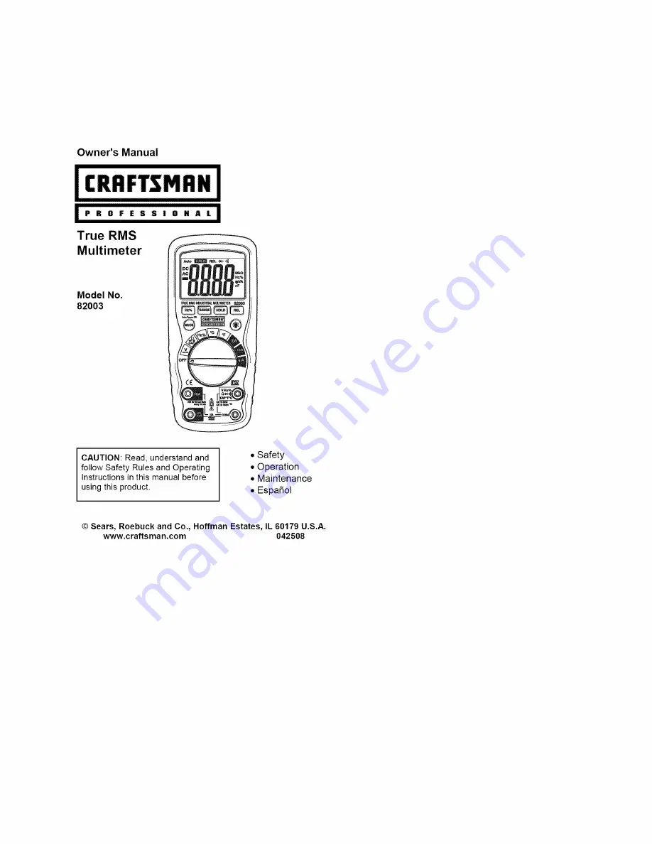
background image

Summary of Contents for 82003

Page 1: ...ter Model No 82003 CAUTION Read understand and follow Safety Rules and Operating Instructions in this manual before using this product Safety Operation Maintenance EspaSol Sears Roebuck and Co Hoffman Estates IL 60179 U S A www craftsman com 042508 ...

Page 2: ... AC Current Measurements Resistance Measurements Continuity Check Diode Test Capacitance Measurements Frequency Duty Cycle Measurements Temperature Measurements Autoranging Manual range selection Relative Mode Display Backlight Hold Auto Power Off Low Battery Indication Maintenance Battery Replacement Fuse Replacement Troubleshooting Service and Parts Page 3 4 5 6 6 7 11 12 12 13 14 15 16 17 17 18...

Page 3: ...ific legal rights and you may also have other rights which vary from state to state Sears Roebuck and Co Hoffman Estates IL 60179 For Customer Assistance Call 9am 5pm ET Monday through Friday 1 888 326 1006 I WARNING USE EXTREME CAUTION IN THE USE OF THIS DEVICE Improper use of this device can result in injury or death Follow all safeguards suggested in this manual in addition to the normal safety...

Page 4: ... Capacitance Frequency Temperature 2 USE EXTREME CAUTION when working with high voltages 3 DO NOT measure voltage if the voltage on the COM input jack exceeds 1000V above earth ground 4 DO NOT measure current of circuits whose voltage is greater than 600V above earth ground 5 NEVER connect the meter leads across a voltage source while the function switch is in the resistance or diode mode Doing so...

Page 5: ...azardous situation which if not avoided may result damage to the product This symbol advises the user that the terminal s so marked must not be connected to a circuit point at which the voltage with respect to earth ground exceeds in this case 1000 VAC or VDC This symbol adjacent to one or more terminals identifies them as being associated with ranges that may in normal use be subjected to particu...

Page 6: ...Tilt stand and battery compartment are on rear of unit H _ k I _ k k k _ O_ Continuity Diode test Battery status n nano 10 9 capacitance p micro 10 8 amps m milli 10 s volts amps A Amps k kilo 103 ohms F Farads capacitance M mega 106 ohms _ Ohms Hz Hertz frequency Percent duty ratio AC Alternating current DC Direct current F Degrees Fahrenheit Auto _ REL M C F V Volts REL Relative Auto Autoranging...

Page 7: ...0 001V 0 01V 0 1V 1V 0 1pA 1pA 0 01 mA 0 1mA 0 01A 0 1pA 1pA 0 01 mA 0 1mA 0 01A 0 1 _ 0 001 k _ 0 01k _ 0 1k _ 0 001M _ 0 01M _ Accuracy 0 5 reading 2 digits 1 2 reading 2 digits 1 5 reading 2 digits 2 0 reading 10 digits 2 0 reading 5 digits 2 5 reading 5 digits 1 0 reading 3 digits 1 5 reading 3 digits 2 5 reading 5 digits 2 5 reading 10 digits 2 5 reading 5 digits 3 0 reading 7 digits 1 2 read...

Page 8: ...ivity 0 5V rms 500kHz 3V rms 500kHz 0 1to99 9 I 0 1 I 1 2 reading 2digits Pulsewidth 100ps 100ms Frequency 5Hzto 150kHz 4to1382 FI 0 1o 400 3 0 reading 5 C 9 F 20 to 750 C I 1 400 probeaccuracynot included SuppliedProberange 58 0 to 482oF 50 0to 250oC Note An optionalprobe that isratedto the full range of the meter is availablefromthe www cra man comwebsite Note Accuracy is stated at 65 F to 83 F ...

Page 9: ... less than 100 _ approx test current 0 3mA Requires type K thermocouple 7 8M 2 True rms 50Hz to 400Hz 3 at full scale up to 500V decreasing linearly to 1 5 at 1O00V 4 000 count backlit liquid crystal OL is displayed 30 minutes approximately Automatic no indication for positive Minus sign for negative 2 times per second nominal 1_ is displayed if battery voltage drops below operating voltage One 9 ...

Page 10: ...N61010 1 and IEC61010 1 2 d Edition 2001 to Category IV 600V and Category III 1000V Pollution Degree 2 The meter also meets UL 61010 1 2 d Edition 2004 CAN CSA C22 2 No 61010 1 2 d Edition 2004 and UL 61010B 2 031 1S_ Edition 2003 UL CE The UL mark does not indicate that this product has been evaluated for the accuracy of its readings 10 ...

Page 11: ...ing two screws B using a Phillips head screwdriver 3 Insert the battery into battery holder observing the correct polarity 4 Put the battery cover back in place Secure with the screws I WARNING To avoid electric shock do not operate the meter until the battery cover is in place and fastened securely NOTE If your meter does not work properly check the fuses and batteries to make sure that they are ...

Page 12: ... caused by the high input sensitivity The reading will stabilize and give a proper measurement when connected to a circuit DC VOLTAGE MEASUREMENTS I CAUTION Do not measure DC voltages if a motor on the I circuit is being switched ON or OFF Large voltage surges may I occur that can damage the meter 1 Set the function switch to the V position 2 Press the MODE button to select DC if necessary 3 Inser...

Page 13: ...sure AC voltages if a motor on the I circuit is being switched ON or OFF Large voltage surges may I occur that can damage the meter 1 Set the function switch to the V position 2 Press the MODE button to select AC if necessary 3 Insert the black test lead banana plug into the negative COM jack Insert red test lead banana plug into the positive V jack 4 Touch the black test probe tip to the neutral ...

Page 14: ...up to 400mA DC set the function switch to the rnA position and insert the red test lead banana plug into the pA mA jack 4 For current measurements up to 10A DC set the function switch to the 10A position and insert the red test lead banana plug into the 10A jack 5 Press the MODE button to indicate DC on the display 6 Remove power from the circuit under test then open up the circuit at the point wh...

Page 15: ...ug into the pA mA jack 4 For current measurements up to 10A AC set the function switch to the 10A position and insert the red test lead banana plug into the 10A jack Press the MODE button to indicate AC on the display 5 6 7 355_ED t I Remove power from the circuit under test then open up the circuit at the point where you wish to measure current Touch the black test probe tip to the neutral side o...

Page 16: ... the Q CAP41_ o position 2 Insert the black test lead banana plug into the negative COM jack Insert the red test lead banana plug into the positive _ jack 3 Press the MODE button to indicate _ on the display 4 Touch the test probe tips across the circuit or part under test It is best to disconnect one side of the part under test so the rest of the circuit will not interfere with the resistance rea...

Page 17: ...k 5 If the resistance is less than approximately 100 2 the audible signal will sound If the circuit is open the display will indicate OL I DIODE TEST 1 Set the function switch to the Q CAP I I o position 2 Insert the black test lead banana plug into the negative COM jack and the red test lead banana plug into the positive V jack 3 Press the MODE button to indicate4N and V on the display 4 Touch th...

Page 18: ...est leads to the capacitor to be tested 5 The test may take up to 3 minutes or more for large capacitors to charge Wait until the readings settle before ending the test 6 Read the capacitance value in the display 4 Touch the test probe tips to the circuit under test 5 Read the frequency on the display 6 Press the Hz button again to indicate on the display 7 Read the of duty cycle on the display FR...

Page 19: ...nnector to banana connector adaptor is supplied for connection to the input banana jacks Note The supplied thermocouple is rated for 482 F 250 C For higher temperatures you can purchase a high temperature thermocouple from www craftsman com FREQUENCY SENSITIVITY ELECTRICAL The frequency sensitivity is range dependent when the function is selected from while in the voltage or current measuring func...

Page 20: ...ive measurement feature allows you to make measurements relative to a stored zero reference value A reference voltage current etc can be stored and measurements made in comparison to that value The displayed value is the difference between the reference value and the measured vaJue 1 Perform the measurement as described in the operating instructions 2 Press the REL button to store zero the reading...

Page 21: ...e meter offafter 30minutes To disable the auto power offfeature hold down the MODE button and turn the meter on LOW BATTERY INDICATION The _ icon will appear inthe display when the battery voltage becomes low Replace the battery when this appears 21 ...

Page 22: ... extremes can shorten the life of the electronic parts and distort or melt plastic parts 3 HANDLE THE METER GENTLY AND CAREFULLY Dropping it can damage the electronic parts or the case 4 KEEP THE METER CLEAN Wipe the case occasionally with a damp cloth DO NOT use chemicals cleaning solvents or detergents 5 USE ONLY FRESH BATTERIES OF THE RECOMMENDED SIZE AND TYPE Remove old or weak batteries so th...

Page 23: ... WARNING To avoid electric shock do not operate the meter I until the battery cover is in place and fastened securely NOTE If your meter does not work properly check the fuses and batteries to make sure that they are still good and that they are properly inserted REPLACING THE FUSES I WARNING To avoid electric shock disconnect the test leads from any source of voltage before removing the fuse cove...

Page 24: ...ow forthe 400mA range SIBA 70 172 40 10A 1000V fast blow forthe 20A range SIBA 50 199 06 6 Replace and secure the rear cover battery and battery cover IWARNING To avoid electric shock donot operate your meter until the fuse cover isinplace and fastened securely 1 24 ...

Page 25: ...be sure the battery is good 4 If the battery is good and the meter still doesn t operate check to be sure that both ends of the fuse are properly installed If You Do Not Understand How the Meter Works Call our Customer Service Line 1 888 326 1006 Item Number Description 82378 Set of black and red Test Leads 82003 D Replacement battery cover 82003 C Front cover 82003 CS Rear cover screws 82377 Ther...

Reviews: