Craftsman 720.25251, Owner'S Manual
The Craftsman 720.25251 is a versatile and reliable tool designed for exceptional performance. To fully understand its features and maximize its potential, it is essential to have the Owner's Manual. Easily download the detailed manual for free from our website manualshive.com, ensuring you have all the necessary information at your fingertips.
Share
Download


Reviews:
No comments
Related manuals for 720.25251
LO 65 Ec
Brand: Mafell Pages: 162
MR 40PB
Brand: Far Tools Pages: 24
TRAK 2OP M11 Mill
Brand: XYZ Machine Tools Pages: 203
YT-82380
Brand: YATO Pages: 96
RO 1600 PLU
Brand: F.F. Group Pages: 56

AceroDURO 100/S100
Brand: CNC-Step Pages: 86
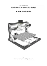
Genmitsu CNC
Brand: SainSmart Pages: 12
3663602796282
Brand: Erbauer Pages: 36
RE180PL1
Brand: Ryobi Pages: 44
52G710
Brand: VERTO Pages: 48

154699.01
Brand: ENKHO Pages: 48
MASLOW CNC
Brand: MAKER MADE Pages: 40
20731
Brand: Yeti Pages: 29
1019072
Brand: Baileigh Pages: 20
TC-RO 850
Brand: EINHELL Pages: 32
241-0836
Brand: MasterForce Pages: 12

RTR18
Brand: Ryobi Pages: 84
PRS1010
Brand: Kreg Pages: 24


