background image

PRINTED IN U.S.A.

Operator's Manual

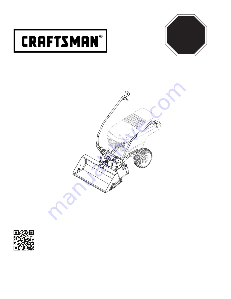
FRONT SCOOP TRACTOR ATTACHMENT 

Model No. 486.248476

FORM NO. 40344  (03/19/15)

CAUTION:

Before using this product, read 
this manual and follow all Safety 
Rules and Operating Instructions.

•  Safety
•  Assembly
•  Operation
•  Maintenance
•  Parts

STOP

DO NOT RETURN TO STORE
For Missing Parts or Assembly
Questions Call 1-866-576-8388

Sears Brands Management Corporation, Hoffman Estates, IL 60179 U.S.A.
www.sears.com/craftsman

Want more information or assembly tips? 
Scan with free ShowUHow Mobile App
available at iTunes Store or Google Play.

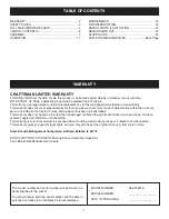
Summary of Contents for 486.248476

Page 1: ...Safety Rules and Operating Instructions Safety Assembly Operation Maintenance Parts STOP DO NOT RETURN TO STORE For Missing Parts or Assembly Questions Call 1 866 576 8388 Sears Brands Management Corporation Hoffman Estates IL 60179 U S A www sears com craftsman Want more information or assembly tips Scan with free ShowUHow Mobile App available at iTunes Store or Google Play ...

Page 2: ...ctive product will be replaced free of charge For warranty coverage details to obtain free replacement visit the web page www craftsman com warranty This warranty does not cover expendable items that can wear out from normal use or deterioration within the warranty period including but not limited to tires belts exterior finishes or product labels This warranty does not apply to a product that is ...

Page 3: ...pping over and loss of control Do not drive too close to a creek or ditch Never ram the scoop into material at high speed Vehicle braking and stability may be affected with the attachment of this scoop Do not fill the scoop to maximum weight capacity without checking the capability of the vehicle to safely drive and stop with the scoop attached Before operating vehicle on any grade hill refer to t...

Page 4: ...4 FULL SIZE HARDWARE CHART W X AA EE L J K I H N A B C D E F G O Q R S P CC V DD M FF GG II HH JJ KK Y T Z BB U ...

Page 5: ... Nylock Nut 1 2 P 48115 2 Nylock Jam Nut 1 2 Q 43015 2 Hex Nut 3 8 R HA21362 10 Nylock Nut 3 8 S 47810 11 Nylock Nut 5 16 T 43064 2 Nut Hex 5 16 U 47189 3 Nylock Nut 1 4 V 43178 1 Nut Hex 1 4 REF PART NO QTY DESCRIPTION W 47171 1 Nylock Nut 10 32 X 23658 2 Spacer 5 8 Long Y 24817 4 Spacer 1 2 Z 43343 4 Hairpin Cotter Long AA 43055 4 Hairpin Cotter Short BB 43010 6 Cotter Pin 1 8 x 1 1 4 CC 43093 2...

Page 6: ... 66258 1 Tilt Anchor Assembly 6 25562 1 Right Long Side Plate 7 25563 1 Left Long Side Plate 8 25722 1 Frame Brace 9 49273 1 Dump Control Rod REF PART NO QTY DESCRIPTION 10 2 Lift Strap Assembly 11 1 Tilt Bracket Assembly 12 49271 1 Dump Handle Tube 13 49264 1 Lift Handle Tube 14 49268 1 Dump Control Pin 15 64968 1 Dump Pivot Bracket 16 1 Dump Handle Tube Extension 17 1 Lift Handle Tube Extension ...

Page 7: ...E SCOOP ASSEMBLY STEP 1 INSTALL TWO BOLTS SEE FIGURE 1 Assemble two 3 8 x 1 1 4 hex bolts D and 3 8 hex nuts Q threading the nut all the way onto the bolt until it is tight against the head of the bolt Install a nut bolt assembly into the bucket assembly and fasten using a 3 8 nylock nut R Tighten Repeat for the other side STEP 2 INSTALL PIN STOP BRACKET SEE FIGURE 1 Install the pin stop bracket t...

Page 8: ...ap assembly to an arm of the lift bracket assembly and then secure with a small 1 2 washer GG and a short hairpin cotter AA Position the lower end of each lift strap assembly to the outside of the lift frame Fasten to the upper front holes in the lift frame using a clevis pin LL 1 2 long spacer Y and short hairpin cotter AA for each assembly NOTE The lift strap assemblies may be installed in the r...

Page 9: ...4 x 1 3 4 HEX BOLT I 1 2 x 1 HEX BOLT C 1 2 HEX LOCK NUT O ARM EXTENSION SPRING 5 16 HEX NUTS T 5 8 SPACERS X 5 16 x 3 1 2 HEX BOLT H STOP BRACKET LONG COMPRESSION SPRING OO FIGURE 7A FIGURE 7B STEP 8 INSTALL STOP BRACKET BOLT SEE FIGURE 7A For lift straps installed in front holes Install the long compression spring OO and then the two 5 8 spacers X onto the 5 16 x 3 1 2 hex bolt H Insert the bolt...

Page 10: ...TALL DUMP CONTROL ROD SEE FIGURE 9 Install a 1 8 x 1 1 4 cotter pin BB into the inside hole in each end of the dump control rod Spread the ends of the cotter pins and wrap around the rod Install a 5 8 washer II onto each end of the control rod Install the dump control rod to the dump pivot bracket and bucket Fasten using two 5 8 washers II and 1 8 x 1 1 4 cotter pins BB Spread the ends of the cott...

Page 11: ...NSION 1 4 NYLOCK NUT U 1 4 x 1 3 4 HEX BOLT I LIFT HANDLE TUBE FIGURE 12 FIGURE 13 INDEX ROD LIFT CABLE CABLE ADJUSTMENT NUTS HOOK LIFT TRIGGER STEP 13 INSTALL LIFT HANDLE TUBE EXTENSION SEE FIGURE 12 Install the lift handle tube extension on the lift handle tube using a 1 4 x 1 3 4 hex bolt I and 1 4 nylock nut U STEP 14 INSTALL LIFT CABLE SEE FIGURE 13 Connect the hooked end of the lift cable in...

Page 12: ... back of the bucket using a hose clip RR a 10 x 5 8 truss head bolt L and a 10 32 nylock nut W SPRING NN SMALL 1 2 WASHER GG CABLE ADJUSTER HOOK DUMP CONTROL PIN PIN STOP BRACKET 3 4 DUMP CONTROL PIN PIN STOP BRACKET FIGURE 16 STEP 17 INSTALL DUMP CONTROL PIN SEE FIGURE 16 Install a small 1 2 washer GG and then the short compression spring NN onto the dump control pin Install the dump control pin ...

Page 13: ... LARGE WASHERS JJ SEE NOTE FIGURE 19 LAWN TRACTORS AND GARDEN TRACTORS WITH SINGLE SUSPENSION BRACKETS STEP 20 INSTALL SIDE PLATES SEE FIGURE 19 Remove any bolts present in the mounting holes on the left side of the tractor frame Do not remove bolts from right side of frame until left side plate has been installed Install the left long side plate on the tractor frame using three 3 8 x 1 carriage b...

Page 14: ... side plate Fasten the left long side plate to the tractor frame using three 3 8 x 1 hex bolts E 3 8 small washers FF and 3 8 lock washers DD If there is a bracket like the one shown with dotted lines use a 3 8 large washer HH as a shim on the rear bolt Do not tighten yet Repeat for the right long side plate STEP 23 INSTALL FRAME BRACE SEE FIGURE 22 Install the frame brace between the side plates ...

Page 15: ...urface For normal use let the bottom of the bucket rest flat on the ground For more aggressive scraping action place 1 4 shims under the rear of the bucket at each end Make sure the two smaller bolts in the tilt bracket and the four bolts in the pin stop bracket are slightly loosened Swing the tilt bracket forward and position the pin stop bracket so the end of the dump control pin inserts into th...

Page 16: ...r to front holes Refer to step 6 on page 8 STOP BOLT TIGHTEN BOLT TILT BRACKET DUMP CONTROL PIN FIGURE 27 STEP 28 ADJUST STOP BOLT SEE FIGURE 27 Keep the scoop locked in the TRANSPORT position Adjust the nuts on the stop bolt in or out until the dump control pin is centered in the slot of the tilt bracket when the tilt bracket is pulled back against the stop bolt Securely tighten the two nuts toge...

Page 17: ...he scoop bucket while it is tilted forward Add wheel weights for improved traction when using the scoop To dump material from the bucket squeeze the dump trigger and push the dump tube handle down Release the trigger before returning the bucket to the upright position To lower the bucket squeeze the lift trigger and then lift up on the lift handle If the trigger is hard to depress you may need to ...

Page 18: ...ach season rinse off the scoop bucket and scoop lift frame Allow to dry thoroughly Paint any exposed metal surfaces to protect from rust Store in a clean dry area MAINTENANCE Service Dates Check for loose fasteners X Cleaning X Lubrication X Before each use After each use Every season Before storage MAINTENANCE SCHEDULE Fill in dates as you complete regular service LUBRICATION Lightly oil all pivo...

Page 19: ...control cable is not adjusted properly 2 Pin stop bracket is not adjusted properly side to side 1 Debris is lodged between bucket assembly and lift frame 1 Apply grease to the bottom slot in the lift bracket where the index rod slides 2 Adjust the tilt stop brackets as instructed on page 16 1 Adjust the tilt bracket and lift straps as instructed on page 16 2 Adjust the stop bolt as instructed on p...

Page 20: ... 11 12 13 51 76 17 18 73 14 15 20 21 16 22 15 15 28 13 27 28 19 42 43 44 45 52 43 42 13 13 52 45 51 42 51 52 45 43 41 54 45 52 40 32 21 70 50 20 56 57 58 68 17 66 49 64 63 14 35 61 60 59 52 45 15 14 13 68 62 10 3 75 74 53 80 69 13 14 31 71 55 48 37 15 64 15 65 44 47 46 1 72 24 8 6 23 26 25 7 10 36 37 39 29 39 ...

Page 21: ...Jam Nut 3 8 16 38 49270 1 Dump Handle Tube Extension 39 711 0309 2 Clevis Pin 5 8 x 1 1 4 40 49271 1 Dump Handle Tube 41 40173 1 Dump Control Cable REF PART NO QTY DESCRIPTION 42 43601 3 Washer 1 59 x 1 032 x 0 60 43 43093 3 Cotter Pin 1 8 x 1 1 2 44 710 0865 3 Hex Bolt 1 2 13 x 1 Grade 5 45 R19212016 6 Flat Washer 5 8 x 1 1 4 x 16 Ga 46 25852 1 Tilt Bracket Extension Strap 47 25851 1 Tilt Bracket...

Page 22: ...22 NOTES ...

Page 23: ... speed on slopes 1 Fold this page along dotted line indicated above 2 Hold page before you so that its left edge is vertically parallel to a tree trunk or other upright structure 3 Sight across the fold in the direction of hill slope you want to measure 4 Compare the angle of the fold with the slope of the hill ONLY RIDE UP AND DOWN HILL NOT ACROSS HILL F O L D A L O N G D O T T E D L I N E T H I ...

Page 24: ...stas a preguntas o problemas y ordenar piezas o pedir servicio para la reparación de su equipo To help us help you register your product at www craftsman com registration Para poderte ayudar mejor registra tu producto en www craftsman com registration Join the Craftsman Club today Receive exclusive member benefits including special pricing and offers project sharing expert advice and SHOP YOUR WAY...

Reviews: