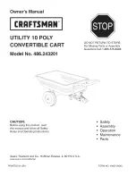
Craftsman 486.243201, Owner'S Manual
The Craftsman 486.243201 Owner's Manual is a must-have for every owner of this product. It provides clear instructions and useful information to help you maximize the performance and durability of your Craftsman 486.243201. Download it for free from manualshive.com and unleash the full potential of your equipment today!
Share
Download
Reviews:
No comments
Related manuals for 486.243201
500
Brand: R&B Wire Products Pages: 2
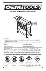
24962
Brand: OEM Tools Pages: 8
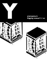
Y Series
Brand: d&b audiotechnik Pages: 8
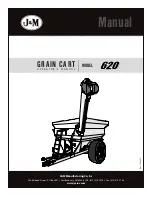
620
Brand: J&M Pages: 38
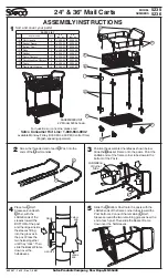
5235
Brand: Safco Pages: 3

Ventura
Brand: Waldbeck Pages: 24
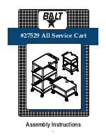
27529
Brand: Balt Pages: 8
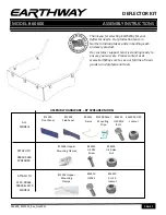
60600
Brand: EarthWay Pages: 5
232
Brand: Gardena Pages: 3

006428
Brand: Hard Head Pages: 11
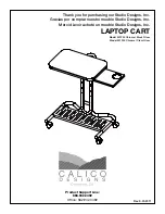
51200
Brand: CALICO DESIGNS Pages: 11
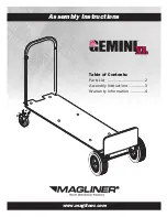
GEMINI XL
Brand: Magliner Pages: 4
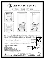
100T
Brand: R&B Wire Products Pages: 2

Crazy Cart
Brand: Razor Pages: 42
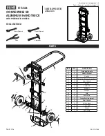
H-1364
Brand: U-Line Pages: 6
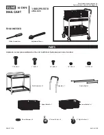
H-1199
Brand: U-Line Pages: 6
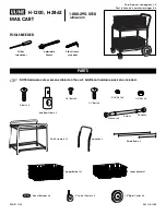
H-1200
Brand: U-Line Pages: 6
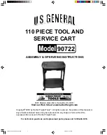
90722
Brand: U.S. General Pages: 6


