background image

Summary of Contents for 486.240383

Page 1: ... CAUTION Read Rules for Safe Operation and Instructions Carefully 38 HiGH PERFORMANCE CRAFTSMAN LAWNSWEEPER Assembly Operation Customer Responsibilities Repair Parts Sears Roebuck and Coo Hoffman Estates IL 60179 U SA PRINTED IN U S A ...

Page 2: ...nuts bolts and screws tight to be sure equipment is in safe working condition 8o Vehicle and attachments should be stopped and inspected for damage after striking a foreign object and damage should be repaired before restarting and operating the equipment 9 Follow maintenance instructions as outlined in this manual Your lawnsweeper carton and inner pack parts carton contains parts as shown in the ...

Page 3: ...x 5 8 OrD X 3116 Hex Nut 5 16 18 Thread Grip Lock Washer 5t16 ID Carriage Bolt 3 8 16 x 1 Long Flat Washers 5 16 Std CONTENTS OF HARDWARE PACK Figure 2 Hopper Bag Assembly AA 6 Truss Slotted Head Screws t0 32 x 5 8 AB 4 Hopper Mounting Clamps AC 6 Hex Lock Nut i0 32 Thread AD 2 Curved Head Bolts 1 4 20 x 1 Long AE 4 Hex Lock Nuts 1 4 20 Thread AF 4 Hex Bolts 5 16 t8 x 3 4 Long AG 4 Hex Lock Nuts 5...

Page 4: ...ARGE FLAT WASHER BRACE ROD FIGURE 5 NOTE FIGURE 3 NOTE Before assembling the hitch bracket or hitch pin bracket to the hitch bar refer to figures 4 7 and page 10 to determine which position is required for your Sears riding mower or tractor 3 Assemble the hitch bracket to hitch bar with one 3 8 x 1 hex bolt in the front hole and 3 8 hex lock nut Do not tighten at this time See figure 4 4 Assemble ...

Page 5: ... the sweeper housing See figure 8 Place 5 16 x 3 4 carriage bolt through the square hole in right hand side of sweeper housing Next place 3 8 flat washer next to housing then spacer into large hole on strap and over end of carriage bolt Secure with 5 16 flat washer 5 16 lock washer and 5 16 hex nut See figure 8 LARGE HOLE IN STRAP 5 16 LOCK WASHER 5_16 x 314 BOLT 111111 SWEEPER HOUSING 5 t6 HEX NU...

Page 6: ... right hand upper hopper tube UPPER HOPPER TUBE LEFT HAND SHOWN BAG FLAP CENTER CUT OUT START 3_ Secure the upper tubes with 1 4 x 1 curved head bolt and hex lock nut See figure 12 114 HEX LOCK NUT INSIDE o 114 x 1 CURVED HEAD BOLT OUTSIDE FIGURE 12 FIGURE 10 2_ Stide the two upper hopper tubes together as shown in figure 11 Line up the center holes UPPER HOPPER TUBES FIGURE 11 Assemb e the two lo...

Page 7: ...OPPER TUBE UPPER ER TUBE 8 HEX LOCK NUT OUTSIDE t _ 3f8 x 3 4 HEX BOLT LOWER HOPPER TUBE _J_ INSIDE HOPPER BAG BOTTOM FIGURE 16 1f4 x 1 1 4 HEX BOLT OUTSIDE FRAME STRAP FIGURE 14 7_ Assemble the bag frame strap bottom and bag retainer top to the front edge of bag bottom Place the bag retainer on top and frame strap on bottom Secure with six t0 x 5 8 slotted screws and 10 32 hex lock nuts See figur...

Page 8: ...le in the tube See figure 19 I2_ Slide pivot _od through hole in side of upper hopper tube that you just pierced in step 11_ Slide one mounting clamp two bag retainer clevises and one more mounting clamp onto rod before rod is pushed into other hole on opposite side of bag See figure 20 MOUNTING CLAMP PIVOT ROD MOUNTING CLAMP FIGURE 20 13 Secure the bag retainer clevis on each side of bag with 1 8...

Page 9: ... bag frame by simply hooking the top corner loops and pull the bottom loops down over the ends of the pivot rod See figure 24 WIND SCREEN TOP CORNER LOOP FIGURE 24 OF PIVOT ROD 17 To assemble the hopper bag frame to the sweeper simply hook the pivot rod into the notches in mounting arms Bag retainers must pivot freely to lock in position See figure 25 18 To remove the hopper bag frame from the swe...

Page 10: ...IGURE 26 THERE ARE EIGHT DIFFERENT SPACER POSITIONS AVAILABLE SEE GROUPS A AND B BRUSH HEIGHT ADJUSTMENT APPROXIMATELY CENTERED APPROXIMATELY LEVEL 5 to 7 FROM SURFACE LEVEL SURFACE FIGURE 26 GROUP A For vehicles with 8 to 10 ground clearance to hitch HITCH BAR WITH HITCH BRACKET MOUNTED BELOW HITCH BAR BLACK LINE IS TRACTOR HITCH TWO SPACERS ABOVE TRACTOR _ ONE SPACER ABOVE AND BELOW TRACTOR _ HI...

Page 11: ... forward to dump See figure 28 SEE CAUTION NOTE A AND Bo Always dump hopper after each use Damp or wet grass and leaves will cause damage to hopper if stored for along period of time A _CAUTION Do Not fasten rope to pulling vehicle where it might become entangled with driving wheels or rotating parts 1t g_ Do Not drive or dump the sweeper too close to a fire as the brushes and bag can be destroyed...

Page 12: ...l the inside with grease Re assemble the wheel and turn wheel if the brushes drive rotate in both directions the pawl is assembled incorrectly remove and flip pawl over If the brushes drive rotate in one direction the pawl is assembled correctly COVER_ GEAR SPROCKE T FIGURE 31 12 COVER AND GREASE FIGURE 32 BRUSH REPLACEMENT 1 Remove the hopper bag from tawnsweeper 2 Brush replacement should be don...

Page 13: ...NOTES 13 ...
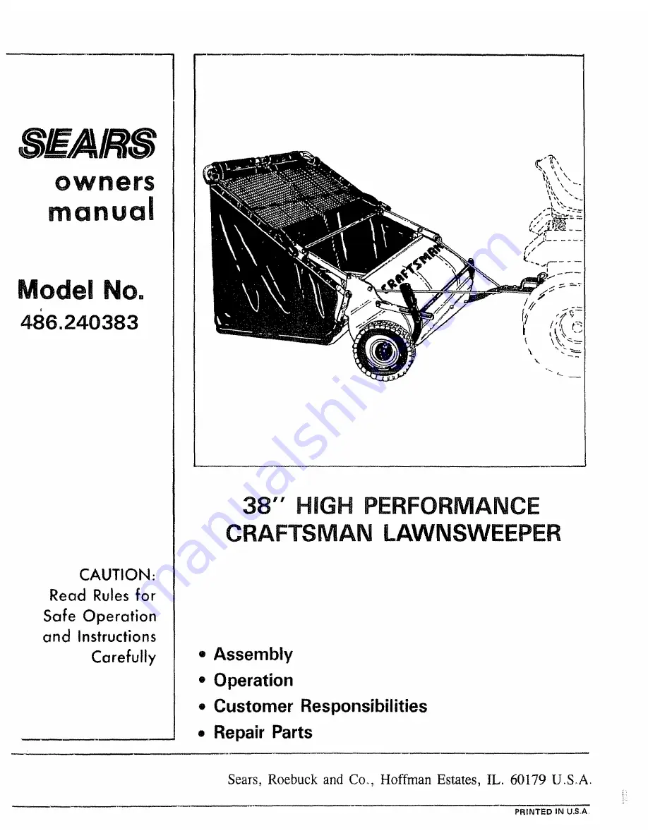
Page 14: ...REPAIR PARTS FOR MODEL 486 240383 38 LAWNSWEEPER OPTIONAL HITCH SHIELD KIT MODEL NOr 486 62718 58 2 8O 6 34 10 7 19 44 1o _7 14 ...

Page 15: ... H 11 1 Washer 51 x 990 x 02 Brace Rod Upper Hopper Tube R H Upper Hopper Tube LH Hopper Bag ER _i0 49 5O 51 52 55 56 57 58 59 60 61 62 63 64 65 66 67 68 69 70 7t 72 73 74 75 76 77 78 79 80 81 86 88 89 90 91 92 93 94 95 PART NO 43937 43968 43969 43938 43737 43086 1540 31 1540 107 43001 43062 43082 R19172410 43182 43064 44008 43407 1509 90 45088 43346 44230 43662 0142 000 43080 23684 44231 43080 62...

Page 16: ...nsweeper is maintained and lubricated according to the operating and maintenance instructions in the owner s manual Seers will repair free of charge any defect in material or workmanship This warranty does not cover repairs necessary because of operator abuse or negligence including the failure to maintain the equipment according to instructions contained in the owner s manual and Lawnsweeper used...

Reviews: