
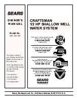

OWNER’S
MANUAL
MODEL NO.
390.252156
CAUTION:
Read and Follow
All Safety Rules and
Operating Instructions
Before First Use of
This Product.
Save This Manual For
Future Reference.
Sears, Roebuck and Co., Hoffman Estates, IL 60179 U.S.A.
• Safety Instructions
• Installation
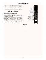
• Electrical
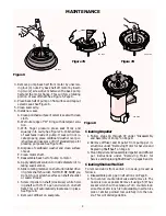
• Maintenance
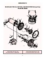
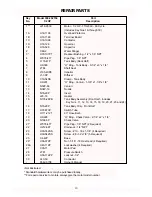
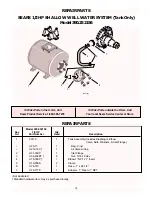
• Repair Parts
PRINTED IN U.S.A.
CRAFTSMAN
1/2 HP SHALLOW WELL
WATER SYSTEM
Form No.
F642-9708
(Rev. 8/4/97)
FOR POSITION ONL
Y
Photo may vary from actual product.
Summary of Contents for 390.252156
Page 15: ...15 ...


