

Summary of Contents for 390.2521
Page 15: ...15 ...
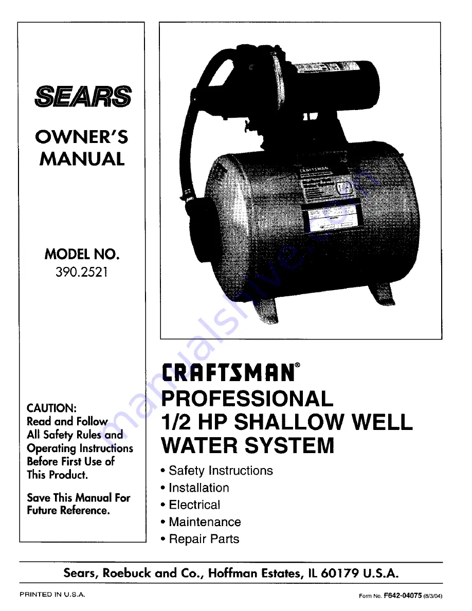
The Craftsman 390.2521 Owner's Manual is a comprehensive guide that provides essential instructions and maintenance tips for the Craftman 390.2521 product. Easily accessible for free download from manualshive.com, this manual equips users with the knowledge they need to maximize the potential of their Craftsman 390.2521.
Page 15: ...15 ...


