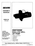
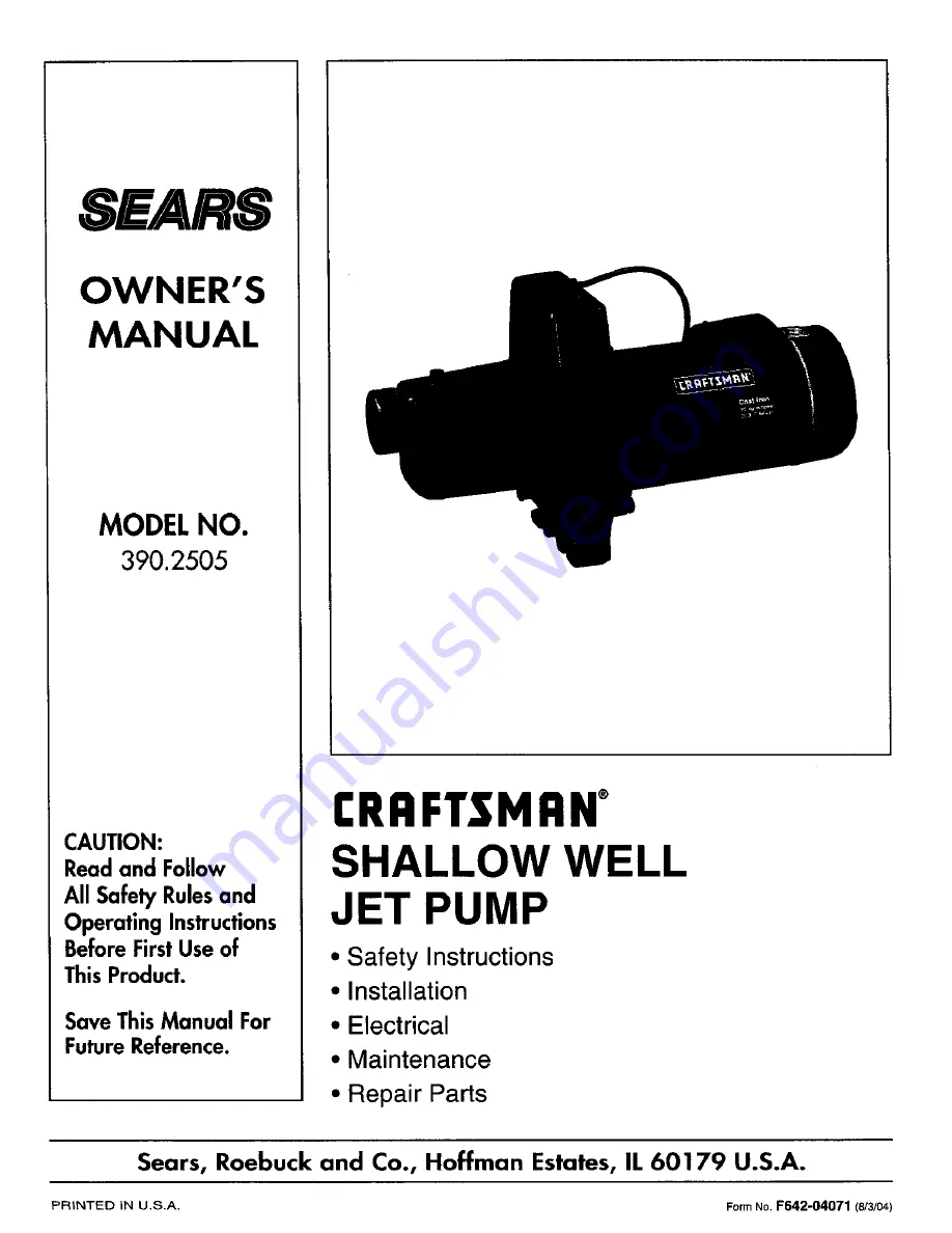
background image

Summary of Contents for 390.2505

Page 1: ...perating Instructions BeforeFirstUse of This Product Save ThisManual For FutureReference I RI IFTSMRN SHALLOW WELL JET PUMP Safety Instructions Installation Electrical Maintenance Repair Parts Sears Roebuck and Co Hoffman Estates IL 60179 U S A PRtNTED iN U S A FormNo F642 04071 8 3 04 ...

Page 2: ...ater and or causing possible serious damage to the me chanical operation of the pump 5 Always test the water from web for purity before using Check with local health department for test ing procedure 6 Before instaUing or servicing your pump BE SURE pump power source is disconnected 7 BE SURE your pump electrical circuit is properly grounded 8 Complete pump and piping system MUST be pre tected aga...

Page 3: ...is information The strainer should not be too close to the bottom or sediment may clog it Before installing foot valve check to see that it works freely When using a foot valve a priming tee and a plug as shown in Figure 1 is recommended Be sure the total lift from the pumping water level to the pump does not exceed 20 feet if the pump is over the well or less if the pump is offset from the well B...

Page 4: ...e end of the tank as shown in Figure 3 Use pipe compound on male threads Screw the air volume control on to the 1 4 fitting and the right angle compression fitting into the bottom tapping of the air volume control Remove the 1 4 pipe plug Key No 13 Page 10 on the jet portion of the pump body near the check valve Insert a 1 4 compression fitting into this tapping Cut tubing to length and assemble t...

Page 5: ...ressure switch If the power supply con nection still needs to be made the pressure switch cover will need to be removed Your motor terminal board located under the motor end cover should look like the one at right Figure 5 Voltage Set To 230 Volts Dial Type To change to I 15 volts 1 Make sure power is off 2 Turn the dial counter clockwise until 115 shows in the dial window 3 Reinstall the Motor en...

Page 6: ...en ground screw Figure 6 Pressure switch wiring 3187 0398 Connection Procedure 1 Connect the ground wire first as shown in Figure 6 The grotmd wire must be a solid copper wire at least as large as the power supply wires 2 There must be a solid metal connection between the pressure switch and the motor for motor grounding protection If the pressure switch is not connected to the motor connect the g...

Page 7: ...h impeller and diffuser can now be removed 685 O294 4echanical sea rotating half 3 Carefully tap diffuser to remove from seal plate 4 Remove canopy from end of motor 5 Partially unscrew capacitor clamp move capacitor to one side 6 Hold motor shaft with 7 16 wrench on the flats on the motor shaft and unscrew impeller SealPlat Removal of Old Seal 1 After unscrewing impeller carefully remove rotat in...

Page 8: ... an ice pick or other small diameter pointed tool into the nozzle and dislodge foreign material If it is not possible to push the obstruction through the nozzle or if the nozzle is damaged follow in structions above under Replacing Venturi 4 Replace all parts Connect motor wiring and turn on power HOW TO HANDLE A GASEOUS WELL In some localities well water contains gases which must be allowed to es...

Page 9: ... have been left open 2 Jet or impeller is clogged 3 Water level in well is lowerthan 4 estimated Motor is wired incorrectly 5 Standard pressure tank is water 1 logged and has no air cushion Pipe leak 2 Faucets or valves are open 3 Foot valve leaks 4 Pressure switch is out of adjustment 5 Air charge too low in 6 Captive Air_ Tank 1 2 3 4 a Re prime according to instructions b Check all connections ...

Page 10: ... 1 Gasket Diffuser 9 N32P 66 1 Venturi 10 N34P 17 1 Nozzle No 43 11 U111 211T 1 Hose Barb 12 2 Pipe Plug 1 4 NPT Hex Head 13 N212 12P 1 Check Valve 14 1 Pipe Plug 1 8 NPT Square Head 15t N176 38A 1 Pump Body Assembly 16 4 Capscrew 3 8 16x1 1 4 Hex Head 17 U37 672P 1 Switch Tube 18 2781 1 Pressure Switch 19 U36 112ZP 1 Locknut 1 2 20 L43 5C 1 Connector t Includes Key Nos 9 10 12 and 13 Standard har...

Page 11: ...ust be purchased separately Key Part No Number Description 34 2761 Air Volume Control 35 U78 774P Reducer Bushing 1 1 4 x 1 4 NPT 36 U37 17GPT Nipple 1 4 x 1 1 2 37 U37 205P Tube AVC 38 U111 86T Compression Fitting Elbow 1 4 NPT 39 U111 100T Compression Fitting Straight 1 8 NPT Standard hardware item Maybe purchased locally ...

Page 12: ...ror replacementpartsyouneed Call7 am 7 pm 7 daysa week 1 800 366 PART 1 800 366 7278 Forin homemajorbrandrepairservice Call24 hours a day 7 daysa week 1 8OO 4 REPAIR 1 800 473 7247 Forthe location of a SearsRepairServiceCenterinyourarea Call24 hours a day 7 daysaweek 1 800 488 1222 Forinformationonpurchasing a Sears MaintenanceAgreement orto inquire aboutan existingAgreement call 9 am 5 pm Monday ...

Reviews: