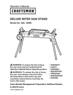
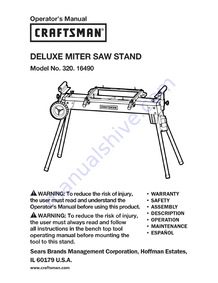
background image

Summary of Contents for 320.16490

Page 1: ...e using this product _WARNING To reduce the risk of injury the user must always read and follow all instructions in the bench top tool operating manual before mounting the tool to this stand WARRANTY SAFETY ASSEMBLY DESCRiPTiON OPERATION MAINTENANCE ESPANOL Sears Brands Management Corporation Hoffman Estates IL 60179 U S A www craftsman com ...

Page 2: ...sit the web site www craftsman com This warranty is void if this product is ever used while providing commercial services or if rented to another person This warranty gives you specific legal rights and you may also have other rights which vary from state to state Sears Brands Management Corporation Hoffman Estates IL 60179 This miter saw work stand has many features for making its use more pleasa...

Page 3: ...s varies depending on how often you do this type of work To reduce your exposure to these chemicals work in a well ventilated area and work with approved safety equipment such as those dust masks that are specially designed to filter out microscopic particles The purpose of safety symbols is to attract your attention to possible dangers The safety symbols and the explanations with them deserve you...

Page 4: ...ry Damage prevention and Information Messages These inform the user of important information and or instructions that could lead to equipment or other property damage if they are not followed Each message is preceded by the word NOTICE as in the example below NOTICE Equipment and or property damage may result if these instructions are not followed _ WARNING To ensure safety and reliability all rep...

Page 5: ...in damp locations To reduce the risk of injury user must Read The Operator s Manual read and understand operator s manual before using this product O Always wear safety goggles or safety Eye Protection glasses with side shields and a full face shield when operating this product _1_ Alert Precautions that involve Safety your safety Failure to keep your hands away from the No Hands Symbol blade will...

Page 6: ...ower tool will increase the risk of electric shock Do not abuse the cord Never use the cord for carrying pulling or unplugging the power tool Keep the cord away from heat oil sharp edges or moving parts Damaged or entangled cords increase the risk of electric shock When operating a power tool outdoors use an extension cord suitable for outdoor use Use of a cord suitable for outdoor use reduces the...

Page 7: ...from moving parts Loose clothes jewelry or long hair can be caught in moving parts Always wear non slip footwear Tie back long hair Roll long sleeves above the elbow Always firmly attach the miter saw used with this stand Do not attempt to use the miter saw on your work stand until the miter saw is fastened firmly Be aware of tipping When a large piece is cut from one end of a job the remaining pi...

Page 8: ...uding legs Roller locking knob wheel Lockin_ lever Quick release mounting brackets Cord Cable hook witch assembly Switch Rating Height Extended width Maximum Load Capacity Weight PRODUCT SEPCIFICATIONS Input voltage 125V AC Input ampere 15 Amps 32 7 8 in 80 in 330 lb 44 lb Page 8 16490 ManuaLRevised_12 0604 ...

Page 9: ...the carton Make sure that all the items listed in the packing list are included Inspect the stand carefully to make sure no that breakage or damage occurred during shipping Do not discard the packing material until you have carefully inspected and satisfactorily operated the stand If any parts are damaged or missing please return the stand to the place of purchase PACKAGE CONTENTS AND HARDWARE ite...

Page 10: ...n bar locking knob 4 K _ Roller assembly locking knob 2 L c _ Roller assembly 2 N _ _ Transport wheel 2 p d_ Wheel clasp 2 Q Wheel mounting axle assembly 1 R _ Wheel mounting bolt 2 S _ Wheel mounting nut 2 Page 10 16490 ManuaLRevised_12 0604 ...

Page 11: ...S 1 Place the frame assembly with legs A upside down on a flat surface as shown in Fig 2 2 To open the top two legs press the locking pins and rotate the legs until the locking pins snap into the open position and you hear a click to signal that the legs are locked in place Fig 3 3 Open and lock the other two legs the same way 4 Place the frame assembly on a flat surface as shown in Fig 4 Fig 2 A ...

Page 12: ... personal injury WARNING To avoid serious personal injury always make sure that miter saws are fully supported and securely attached to a level work surface If necessary move the stand to a location where it will be more stable _ WARNING Do not mount a table saw on this stand The direction of feed on a table saw is perpendicular the axis of stability on this stand Aggressive feeding of sheet mater...

Page 13: ...ASE MOUNTING BRACKETS 1 Hold the quick release mounting bracket B by the handles 2 Position the area designated Z in Fig 8 on the frame assembly A 3 Press the handle down to mount the quick release mounting brackets B 4 Tighten the locking lever to lock the mounting brackets B Fig 9 Fig 8 B Fig 9 _ Locking 16490 Manual_Revised_12 0604 Page 13 ...

Page 14: ...e quick release mounting brackets B Figs 10 and 11 2 Position your miter saw with non standard mounting holes on the cross support bars C Check the position and adjust the support bars slowly so that the mounting holes on the miter saw are aligned with the slots on the cross support bars Fig 12 3 Use the miter saw mounting bolts F washers G spring washers H and locking nuts I to securely tighten t...

Page 15: ...S 1 Insert the roller assemblies L into the mounting slots Fig 14 2 Adjust the height of the roller assemblies L as needed 3 Lock the roller assembly in position by tightening the locking knob K Fig 15 4 A roller assembly may also be used as a stationary stop guide for repetitive cuts Fig 14 St p_ii Fig 15 K 16490 Manual_Revised_12 0604 Page 15 ...

Page 16: ...sembly works as an stop guide to cut the workpieces to the length required Fig 16 When using the roller assembly as a single roller place the workpiece on the roller for convenient operation Fig 17 IFig 16 Stop guide Steel plate ADJUSTING THE EXTENSION BARS Fig 18 1 Extend the extension bar to the required position to properly support the workpiece 2 Fully tighten the two extension bar locking kno...

Page 17: ...tand assembly on its side on a flat surface as shown in Fig 19 2 To fold up the legs depress the locking pin Fig 3 and rotate the legs into position you will hear a click to signal that the legs are locked in place Fig 20 3 Check and tighten all the mounting bolts and nuts 4 Lift the stand and move it as shown in Fig 21 Fig 19 Fig 20 Fig 21 16490 Manual_Revised_12 0604 Page 17 ...

Page 18: ...letely inserted into the switch before the switch panel black can be turned ON Figs 22 and 23 Two receptacles are located at the back of the switch assembly Fig 24 One is intended to supply power to your tool the other one can supply power to a worklight vacuum cleaner or other items The ON OFF switch panel controls power to both outlets Fig 22 Fig 24 J Page 18 16490 ManuaLRevised_12 0604 ...

Page 19: ...on press the switch panel to turn the power OFF and remove the safety key from the switch panel _ WARNING Never leave a tool unattended while it is running or before it comes to a complete stop Circuit Breaker When the switch assembly current exceeds a safe level it will overload the circuit and the circuit breaker will trip Press the circuit breaker button to reset the switch assembly Fig 26 Fig ...

Page 20: ...ensure safety and reliability all repairs should be performed by a qualified service technician _WARNING Keep the miter saw stand dry clean and free from oil and grease Always use a clean cloth when cleaning Never use brake fluids gasoline petroleum based products or any strong solvent to clean the bench grinder stand Chemicals can damage weaken or destroy plastic which may result in serious perso...

Page 21: ...he Nameplate attached to the support leg of the bench grinder stand Always mention the Model Number when ordering parts for this tool To order parts call 1 800 469 4663 Ii IO 9 8 7 6 5 4 3 33 34 53 29 32 31 29 30 16 28 52 51 36 48 I 37 38 4o 16490 Manual_Revised_12 0604 Page 21 ...

Page 22: ...t 2 5 1020211002 Hand wheel 2 6 1021501001 Insert block 4 7 1020904001 Bushing 2 8 2050509006 Roller support 2 9 2040701003 Roller 2 10 1020505001 Cover 4 11 1010101002 Screw 4 12 1010203002 Extension bar 2 13 1010122025 Screw 4 14 1021504001 Block 4 15 1021501002 Block 4 16 1010202004 Nut 14 17 2040107005 Brackets 2 18 1020103002 Locking lever 2 19 1020801002 Connector 2 20 1021601002 Square bloc...

Page 23: ...03 Frame assembly 1 38 1029913012 Switch assembly 1 39 1010122009 Screw 3 40 2029903007 Leg 1 41 1021503001 Block 4 42 1010118004 Bolt 4 43 1010407001 Bolt 4 44 1010603017 Spring 4 45 1010202001 Nut 4 46 1010301001 Washer 4 47 1010602001 Shield ring 4 48 2040102001 Leg 3 49 1020906006 Footpad 4 50 1010122033 Screw 2 51 1020403007 Terminal block 1 52 1010132004 Screw 1 53 1010303003 Spring washer 8...

Page 24: ...al de Operaci6n antes de usar este producto ADVERTENCIA Para reducir el riesgo de lesiones el usuario siempre debe leer y seguir las instrucciones del manual del propietario de la herramienta antes de instalarla GARANTiA SEGURIDAD NIONTAJE DESCRIPCION OPERACi6N MANTENIMIENTO ESPANOL Sears Brands Management Corporation Hoffman Estates IL 60179 U S A www craftsman com ...

Page 25: ... obtener una devoluci6n gratuita visite la p_gina web www craftsman com Esta garantia se anulara si el producto ha sido usado mientras se proveia servicios comerciales o si se ha rentado a otra persona Esta garantia le otorga derechos legales especificos Puede que usted tenga otros derechos que varien de un Estado a otro Corporacion Sears Brands Management Hoffman Estates IL 60179 Esta sierra de i...

Page 26: ... estos quimicos varia dependiendo de cuan frecuente realice este tipo de trabajo Para reducir el contacto con estos quimicos trabaje en un Area bien ventilada y con equipo con seguridad aprobada tales como mascaras para el polvo que esten especialmente dise_adas para filtrar las particulas microscopicas El proposito de los simbolos de seguridad es el de dirigir su atencion hacia los peligros posib...

Page 27: ...ensajes informativos Le informan al usuario de informacion importante y o instrucciones que podrian producir daSo al equipo u otra propiedad si no se cumplen Cada mensaje esta precedido por la palabra NOTA como se muestra en el ejemplo aqui abajo AVlSO Da_o al equipo u o otra propiedad puede producirse si no se cumplen estas instrucciones _ ADVERTENClA para asegurarse la seguridad y la confiabilid...

Page 28: ... Para reducir et riesgo de lesiones et usuario Lea et manual de debe leer y comprender este manual de operaci6n operaci6n antes de usar este producto O Siempre use gafas o lentes de seguridad Protecci6n ocular con protecciones laterales y una protecci6n de todo el rostro cuando utilice este producto _1_ Aterta de seguridad Precauciones que involucran su seguridad Simbolo de no tocar No mantener su...

Page 29: ...su cuerpo tiene conexion a tierra No exponga las herramientas el_ctricas a la lluvia o a condiciones de humedad El agua que ingresa a la herramienta electrica incrementarA el riesgo de una descarga electrica No maltrate el cable Nunca utilice el cable para trasladar o desenchufar la herramienta el6ctrica ni tire del mismo Mantenga el cable alejado del calor aceite bordes afilados o piezas en movim...

Page 30: ...tase adecuadamente No use vestimenta suelta o joyas Mantenga su cabello ropa y guantes alejados de las piezas en movimiento La ropa holgada joyas o cabello largo pueden engancharse en las piezas en movimiento Siempre utilice calzado anti deslizante Los operarios de cabello largo deben atarlo Arrem nguese las mangas largas hasta el codo Siempre sujete firmernente la sierra de inglete utilizada con ...

Page 31: ...Soportes de montaje Palanca de liberacion rApida de bloqueo Cable Perilla de bloqueo de rodillo Montaje del interruptor Rueda para transporte ESPECIFiCACIONES DE PRODUCTO Clasificacion de interruptor Altura Anchura extendida Capacidad de carga maxima Peso Voltaje de entrada Amperios de entrada 32 7 8 pulg 80 pulgadas 330 lb 44 lb 125V CA 15 Amp Page 31 16490 ManuaLRevisado_12 0604 ...

Page 32: ...n la lista de empaque esten incluidos Inspeccione el soporte con cuidado para constatar que no hayan ocurrido roturas o da_os durante el envio No descarte el material de empaque hasta que haya inspeccionado el soporte con cuidado y Io haya utilizado satisfactoriamente Si falta alguna pieza o alguna pieza se encuentra rota tenga a bien devolver el soporte al lugar de compra CONTENIDOS Y PIET_ ASDE ...

Page 33: ...xtension 4 Perilla de bloqueo de montaje 2 K _ de rodillo L d_ Montaje de rodillo 2 N Rueda para transporte 2 P _ Presilla para rueda 2 Montaje de eje de montaje 1 Q de rueda R Perno de montaje de rueda 2 S _ Tuerca de montaje de rueda 2 Page 33 16490 ManuaLRevisado_12 0604 ...

Page 34: ...el armazon con patas A dado vuelta sobre una superficie plana como se indica en la Fig 2 2 Para abrir las dos patas superiores presione las clavijas de bloqueo y gire las patas hasta que las clavijas de bloqueo se traben en la posicion abierta y usted oiga un clic que indica que las patas se hayan trabadas Fig 3 3 Abra y trabe las otras dos patas de la misma manera 4 Coloque el montaje del armazon...

Page 35: ...MO INSTALAR SIERRAS DE INGLETE _IL ADVERTENCIA No desenchufar la herramienta antes de sujetarla al soporte puede provocar un encendido accidental y una lesion personal grave _ ADVERTENClA Para evitar lesiones personales graves siempre verifique que las sierras de inglete esten completamente sostenidas y sujetas a una superficie de trabajo nivelada Si fuera necesario traslade el soporte a una ubica...

Page 36: ... F arandelas G arandelas de resorte H y tuercas de bloqueo I Fig 6 2 Con la sierra de inglete instalada en los soportes de montaje de liberacion rapida coloque el montaje sobre el soporte de trabajo Fig 7 COMO INSTALAR LOS SOPORTES DE MONTAJE DE LIBERACION RAPIDA 1 Sostenga el soporte de montaje de liberacion rapida B de las manijas 2 Coloque el Area denominada Z en la Fig 8 en el montaje del arma...

Page 37: ...s los 3 orificios de montaje forman un patron triangular pocas sierras 1 Coloque dos barras de soporte C en los soportes de montaje B Utilice los pernos de montaje de la barra de soporte D arandelas E arandelas de resorte H y tuercas de bloqueo I para pre ajustar las barras de soporte C en los soportes de montaje de liberacion rapida B Figs 10 y 11 Fig 9 _ Palanca Fig 10 Fig 11 C Dos barras de sop...

Page 38: ...esorte H y tuercas de bloqueo I para ajustar bien la sierra a las barras de soporte C 4 Ajuste lastuercas de bloqueo I para ajustar por completo la barra de soporte C 5 Con la sierra de inglete instalada en los soportes de montaje de liberacion rapida B coloque el montaje sobre el soporte de trabajo Fig 13 COMO INSTALAR LOS MONTAJES DE RODILLO 1 Introduzca los montajes de rodillo L en las ranuras ...

Page 39: ...tope coloque la pieza de trabajo sobre la placa el montaje de rodillo funciona como una guia de tope para cortar las piezas de trabajo con la Iongitud requerida Fig 16 Cuando utilice el montaje de rodillo como un rodillo Onico coloque la pieza de trabajo sobre el rodillo para un funcionamiento conveniente Fig 17 COMO AJUSTAR LAS EXTENSION Fig 18 1 Extienda la barra de extension hasta la posicion r...

Page 40: ...mazon sobre su lado en una superficie plana como se indica en la Fig 19 2 Para plegar las patas baje la clavija de bloqueo Fig 3 y gire las patas hasta su posicion se oirA un clic que indica que las patas se hallan trabadas en su lugar Fig 20 3 Verifique y ajustetodos los pemos y tuercas de montaje 4 Levante el soporte y trasl delo como se indica en la Fig 21 Fig 19 Fig 20 Fig 21 16490 Manual_Revi...

Page 41: ...ucirse por completo en el interruptor antes de que el panel del interruptor negro pueda encenderse Figs 22 y 23 Hay dos receptaculos en la parte trasera del montaje de interruptor Fig 24 Uno suministra energia a la herramienta el otro puede suministrar energia a la luz de trabajo aspiradora y otros elementos El panel del interruptor On Off encendido apagado controla la energia hacia ambos tomacorr...

Page 42: ...pagado OFF presione el panel del interruptor para apagar la energia OFF y quite la Ilave de seguridad del panel del interruptor _ ADVERTENCIA Nunca deje una herramienta sin atencion mientras se encuentra funcionando o antes de que se detenga por completo Circuit Breaker Interruptor de circuito Cuando la corriente del montaje del interruptor supera un nivel seguro el circuito sufrir una sobrecarga ...

Page 43: ...as reparaciones deben set efectuadas pot un tecnico calificado _I_ ADVERTENClA Mantenga el soporte de la sierra de inglete seco limpio y libre de aceite o grasa Siempre utilice un patio limpio cuando realice su limpieza Nunca utilice liquido de frenos gasolina productos a base de petroleo o solventes potentes para limpiar el soporte de amoladora de banco Los productos quimicos pueden dafiar debili...

Page 44: ... placa sujeta a la pata de soporte del soporte Siempre mencione el nOmero de modelo cuando solicite repuestos para esta herramienta Para solicitar repuestos Ilame al 1 800 469 4663 Ii IO 9 8 7 6 5 4 3 33 34 53 29 32 29 30 I 16 28 52 51 36 48 37 38 4O 16490 Manual_Revisado_ 2 0604 Page 44 ...

Page 45: ...20211002 Rueda de mano 2 6 1021501001 Bloque de montaje 4 7 1020904001 Casquillo 2 8 2050509006 Soporte del rodillo 2 9 2040701003 Rodillo 2 10 1020505001 Cubierta 4 11 1010101002 Tornillo 4 12 1010203002 Barra de extension 2 13 1010122025 Tornillo 4 14 1021504001 Bloque 4 15 1021501002 Bloque 4 16 1010202004 Tuerca 14 17 2040107005 Soporte de montaje 2 18 1020103002 Palanca de bloqueo 2 19 102080...

Page 46: ...taje del interruptor 39 1010122009 Tornillo 40 2029903007 Pata 41 1021503001 Bloque 42 1010118004 Perno 43 1010407001 Perno 44 1010603017 Resorte 45 1010202001 Tuerca 46 1010301001 Arand ela 47 1010602001 Anillo de proteccion 48 2040102001 Pata 49 1020906006 Almohadilla de la pata 50 1010122033 Tornillo 51 1020403007 Bloque terminal 52 1010132004 Tornillo 53 1010303003 Arandela 54 1010301007 Arand...

Page 47: ...e using this product _WARNING To reduce the risk of injury the user must always read and follow all instructions in the bench top tool operating manual before mounting the tool to this stand WARRANTY SAFETY ASSEMBLY DESCRiPTiON OPERATION MAINTENANCE ESPANOL Sears Brands Management Corporation Hoffman Estates IL 60179 U S A www craftsman com ...

Page 48: ...sit the web site www craftsman com This warranty is void if this product is ever used while providing commercial services or if rented to another person This warranty gives you specific legal rights and you may also have other rights which vary from state to state Sears Brands Management Corporation Hoffman Estates IL 60179 This miter saw work stand has many features for making its use more pleasa...

Page 49: ...s varies depending on how often you do this type of work To reduce your exposure to these chemicals work in a well ventilated area and work with approved safety equipment such as those dust masks that are specially designed to filter out microscopic particles The purpose of safety symbols is to attract your attention to possible dangers The safety symbols and the explanations with them deserve you...

Page 50: ...ry Damage prevention and Information Messages These inform the user of important information and or instructions that could lead to equipment or other property damage if they are not followed Each message is preceded by the word NOTICE as in the example below NOTICE Equipment and or property damage may result if these instructions are not followed _ WARNING To ensure safety and reliability all rep...

Page 51: ...in damp locations To reduce the risk of injury user must Read The Operator s Manual read and understand operator s manual before using this product O Always wear safety goggles or safety Eye Protection glasses with side shields and a full face shield when operating this product _1_ Alert Precautions that involve Safety your safety Failure to keep your hands away from the No Hands Symbol blade will...

Page 52: ...ower tool will increase the risk of electric shock Do not abuse the cord Never use the cord for carrying pulling or unplugging the power tool Keep the cord away from heat oil sharp edges or moving parts Damaged or entangled cords increase the risk of electric shock When operating a power tool outdoors use an extension cord suitable for outdoor use Use of a cord suitable for outdoor use reduces the...

Page 53: ...from moving parts Loose clothes jewelry or long hair can be caught in moving parts Always wear non slip footwear Tie back long hair Roll long sleeves above the elbow Always firmly attach the miter saw used with this stand Do not attempt to use the miter saw on your work stand until the miter saw is fastened firmly Be aware of tipping When a large piece is cut from one end of a job the remaining pi...

Page 54: ...uding legs Roller locking knob wheel Lockin_ lever Quick release mounting brackets Cord Cable hook witch assembly Switch Rating Height Extended width Maximum Load Capacity Weight PRODUCT SEPCIFICATIONS Input voltage 125V AC Input ampere 15 Amps 32 7 8 in 80 in 330 lb 44 lb Page 8 16490 ManuaLRevised_12 0604 ...

Page 55: ...the carton Make sure that all the items listed in the packing list are included Inspect the stand carefully to make sure no that breakage or damage occurred during shipping Do not discard the packing material until you have carefully inspected and satisfactorily operated the stand If any parts are damaged or missing please return the stand to the place of purchase PACKAGE CONTENTS AND HARDWARE ite...

Page 56: ...n bar locking knob 4 K _ Roller assembly locking knob 2 L c _ Roller assembly 2 N _ _ Transport wheel 2 p d_ Wheel clasp 2 Q Wheel mounting axle assembly 1 R _ Wheel mounting bolt 2 S _ Wheel mounting nut 2 Page 10 16490 ManuaLRevised_12 0604 ...

Page 57: ...S 1 Place the frame assembly with legs A upside down on a flat surface as shown in Fig 2 2 To open the top two legs press the locking pins and rotate the legs until the locking pins snap into the open position and you hear a click to signal that the legs are locked in place Fig 3 3 Open and lock the other two legs the same way 4 Place the frame assembly on a flat surface as shown in Fig 4 Fig 2 A ...

Page 58: ... personal injury WARNING To avoid serious personal injury always make sure that miter saws are fully supported and securely attached to a level work surface If necessary move the stand to a location where it will be more stable _ WARNING Do not mount a table saw on this stand The direction of feed on a table saw is perpendicular the axis of stability on this stand Aggressive feeding of sheet mater...

Page 59: ...ASE MOUNTING BRACKETS 1 Hold the quick release mounting bracket B by the handles 2 Position the area designated Z in Fig 8 on the frame assembly A 3 Press the handle down to mount the quick release mounting brackets B 4 Tighten the locking lever to lock the mounting brackets B Fig 9 Fig 8 B Fig 9 _ Locking 16490 Manual_Revised_12 0604 Page 13 ...

Page 60: ...e quick release mounting brackets B Figs 10 and 11 2 Position your miter saw with non standard mounting holes on the cross support bars C Check the position and adjust the support bars slowly so that the mounting holes on the miter saw are aligned with the slots on the cross support bars Fig 12 3 Use the miter saw mounting bolts F washers G spring washers H and locking nuts I to securely tighten t...

Page 61: ...S 1 Insert the roller assemblies L into the mounting slots Fig 14 2 Adjust the height of the roller assemblies L as needed 3 Lock the roller assembly in position by tightening the locking knob K Fig 15 4 A roller assembly may also be used as a stationary stop guide for repetitive cuts Fig 14 St p_ii Fig 15 K 16490 Manual_Revised_12 0604 Page 15 ...

Page 62: ...sembly works as an stop guide to cut the workpieces to the length required Fig 16 When using the roller assembly as a single roller place the workpiece on the roller for convenient operation Fig 17 IFig 16 Stop guide Steel plate ADJUSTING THE EXTENSION BARS Fig 18 1 Extend the extension bar to the required position to properly support the workpiece 2 Fully tighten the two extension bar locking kno...

Page 63: ...tand assembly on its side on a flat surface as shown in Fig 19 2 To fold up the legs depress the locking pin Fig 3 and rotate the legs into position you will hear a click to signal that the legs are locked in place Fig 20 3 Check and tighten all the mounting bolts and nuts 4 Lift the stand and move it as shown in Fig 21 Fig 19 Fig 20 Fig 21 16490 Manual_Revised_12 0604 Page 17 ...

Page 64: ...letely inserted into the switch before the switch panel black can be turned ON Figs 22 and 23 Two receptacles are located at the back of the switch assembly Fig 24 One is intended to supply power to your tool the other one can supply power to a worklight vacuum cleaner or other items The ON OFF switch panel controls power to both outlets Fig 22 Fig 24 J Page 18 16490 ManuaLRevised_12 0604 ...

Page 65: ...on press the switch panel to turn the power OFF and remove the safety key from the switch panel _ WARNING Never leave a tool unattended while it is running or before it comes to a complete stop Circuit Breaker When the switch assembly current exceeds a safe level it will overload the circuit and the circuit breaker will trip Press the circuit breaker button to reset the switch assembly Fig 26 Fig ...

Page 66: ...ensure safety and reliability all repairs should be performed by a qualified service technician _WARNING Keep the miter saw stand dry clean and free from oil and grease Always use a clean cloth when cleaning Never use brake fluids gasoline petroleum based products or any strong solvent to clean the bench grinder stand Chemicals can damage weaken or destroy plastic which may result in serious perso...

Page 67: ...he Nameplate attached to the support leg of the bench grinder stand Always mention the Model Number when ordering parts for this tool To order parts call 1 800 469 4663 Ii IO 9 8 7 6 5 4 3 33 34 53 29 32 31 29 30 16 28 52 51 36 48 I 37 38 4o 16490 Manual_Revised_12 0604 Page 21 ...

Page 68: ...t 2 5 1020211002 Hand wheel 2 6 1021501001 Insert block 4 7 1020904001 Bushing 2 8 2050509006 Roller support 2 9 2040701003 Roller 2 10 1020505001 Cover 4 11 1010101002 Screw 4 12 1010203002 Extension bar 2 13 1010122025 Screw 4 14 1021504001 Block 4 15 1021501002 Block 4 16 1010202004 Nut 14 17 2040107005 Brackets 2 18 1020103002 Locking lever 2 19 1020801002 Connector 2 20 1021601002 Square bloc...

Page 69: ...03 Frame assembly 1 38 1029913012 Switch assembly 1 39 1010122009 Screw 3 40 2029903007 Leg 1 41 1021503001 Block 4 42 1010118004 Bolt 4 43 1010407001 Bolt 4 44 1010603017 Spring 4 45 1010202001 Nut 4 46 1010301001 Washer 4 47 1010602001 Shield ring 4 48 2040102001 Leg 3 49 1020906006 Footpad 4 50 1010122033 Screw 2 51 1020403007 Terminal block 1 52 1010132004 Screw 1 53 1010303003 Spring washer 8...

Page 70: ...al de Operaci6n antes de usar este producto ADVERTENCIA Para reducir el riesgo de lesiones el usuario siempre debe leer y seguir las instrucciones del manual del propietario de la herramienta antes de instalarla GARANTiA SEGURIDAD NIONTAJE DESCRIPCION OPERACi6N MANTENIMIENTO ESPANOL Sears Brands Management Corporation Hoffman Estates IL 60179 U S A www craftsman com ...

Page 71: ... obtener una devoluci6n gratuita visite la p_gina web www craftsman com Esta garantia se anulara si el producto ha sido usado mientras se proveia servicios comerciales o si se ha rentado a otra persona Esta garantia le otorga derechos legales especificos Puede que usted tenga otros derechos que varien de un Estado a otro Corporacion Sears Brands Management Hoffman Estates IL 60179 Esta sierra de i...

Page 72: ... estos quimicos varia dependiendo de cuan frecuente realice este tipo de trabajo Para reducir el contacto con estos quimicos trabaje en un Area bien ventilada y con equipo con seguridad aprobada tales como mascaras para el polvo que esten especialmente dise_adas para filtrar las particulas microscopicas El proposito de los simbolos de seguridad es el de dirigir su atencion hacia los peligros posib...

Page 73: ...ensajes informativos Le informan al usuario de informacion importante y o instrucciones que podrian producir daSo al equipo u otra propiedad si no se cumplen Cada mensaje esta precedido por la palabra NOTA como se muestra en el ejemplo aqui abajo AVlSO Da_o al equipo u o otra propiedad puede producirse si no se cumplen estas instrucciones _ ADVERTENClA para asegurarse la seguridad y la confiabilid...

Page 74: ... Para reducir et riesgo de lesiones et usuario Lea et manual de debe leer y comprender este manual de operaci6n operaci6n antes de usar este producto O Siempre use gafas o lentes de seguridad Protecci6n ocular con protecciones laterales y una protecci6n de todo el rostro cuando utilice este producto _1_ Aterta de seguridad Precauciones que involucran su seguridad Simbolo de no tocar No mantener su...

Page 75: ...su cuerpo tiene conexion a tierra No exponga las herramientas el_ctricas a la lluvia o a condiciones de humedad El agua que ingresa a la herramienta electrica incrementarA el riesgo de una descarga electrica No maltrate el cable Nunca utilice el cable para trasladar o desenchufar la herramienta el6ctrica ni tire del mismo Mantenga el cable alejado del calor aceite bordes afilados o piezas en movim...

Page 76: ...tase adecuadamente No use vestimenta suelta o joyas Mantenga su cabello ropa y guantes alejados de las piezas en movimiento La ropa holgada joyas o cabello largo pueden engancharse en las piezas en movimiento Siempre utilice calzado anti deslizante Los operarios de cabello largo deben atarlo Arrem nguese las mangas largas hasta el codo Siempre sujete firmernente la sierra de inglete utilizada con ...

Page 77: ...Soportes de montaje Palanca de liberacion rApida de bloqueo Cable Perilla de bloqueo de rodillo Montaje del interruptor Rueda para transporte ESPECIFiCACIONES DE PRODUCTO Clasificacion de interruptor Altura Anchura extendida Capacidad de carga maxima Peso Voltaje de entrada Amperios de entrada 32 7 8 pulg 80 pulgadas 330 lb 44 lb 125V CA 15 Amp Page 31 16490 ManuaLRevisado_12 0604 ...

Page 78: ...n la lista de empaque esten incluidos Inspeccione el soporte con cuidado para constatar que no hayan ocurrido roturas o da_os durante el envio No descarte el material de empaque hasta que haya inspeccionado el soporte con cuidado y Io haya utilizado satisfactoriamente Si falta alguna pieza o alguna pieza se encuentra rota tenga a bien devolver el soporte al lugar de compra CONTENIDOS Y PIET_ ASDE ...

Page 79: ...xtension 4 Perilla de bloqueo de montaje 2 K _ de rodillo L d_ Montaje de rodillo 2 N Rueda para transporte 2 P _ Presilla para rueda 2 Montaje de eje de montaje 1 Q de rueda R Perno de montaje de rueda 2 S _ Tuerca de montaje de rueda 2 Page 33 16490 ManuaLRevisado_12 0604 ...

Page 80: ...el armazon con patas A dado vuelta sobre una superficie plana como se indica en la Fig 2 2 Para abrir las dos patas superiores presione las clavijas de bloqueo y gire las patas hasta que las clavijas de bloqueo se traben en la posicion abierta y usted oiga un clic que indica que las patas se hayan trabadas Fig 3 3 Abra y trabe las otras dos patas de la misma manera 4 Coloque el montaje del armazon...

Page 81: ...MO INSTALAR SIERRAS DE INGLETE _IL ADVERTENCIA No desenchufar la herramienta antes de sujetarla al soporte puede provocar un encendido accidental y una lesion personal grave _ ADVERTENClA Para evitar lesiones personales graves siempre verifique que las sierras de inglete esten completamente sostenidas y sujetas a una superficie de trabajo nivelada Si fuera necesario traslade el soporte a una ubica...

Page 82: ... F arandelas G arandelas de resorte H y tuercas de bloqueo I Fig 6 2 Con la sierra de inglete instalada en los soportes de montaje de liberacion rapida coloque el montaje sobre el soporte de trabajo Fig 7 COMO INSTALAR LOS SOPORTES DE MONTAJE DE LIBERACION RAPIDA 1 Sostenga el soporte de montaje de liberacion rapida B de las manijas 2 Coloque el Area denominada Z en la Fig 8 en el montaje del arma...

Page 83: ...s los 3 orificios de montaje forman un patron triangular pocas sierras 1 Coloque dos barras de soporte C en los soportes de montaje B Utilice los pernos de montaje de la barra de soporte D arandelas E arandelas de resorte H y tuercas de bloqueo I para pre ajustar las barras de soporte C en los soportes de montaje de liberacion rapida B Figs 10 y 11 Fig 9 _ Palanca Fig 10 Fig 11 C Dos barras de sop...

Page 84: ...esorte H y tuercas de bloqueo I para ajustar bien la sierra a las barras de soporte C 4 Ajuste lastuercas de bloqueo I para ajustar por completo la barra de soporte C 5 Con la sierra de inglete instalada en los soportes de montaje de liberacion rapida B coloque el montaje sobre el soporte de trabajo Fig 13 COMO INSTALAR LOS MONTAJES DE RODILLO 1 Introduzca los montajes de rodillo L en las ranuras ...

Page 85: ...tope coloque la pieza de trabajo sobre la placa el montaje de rodillo funciona como una guia de tope para cortar las piezas de trabajo con la Iongitud requerida Fig 16 Cuando utilice el montaje de rodillo como un rodillo Onico coloque la pieza de trabajo sobre el rodillo para un funcionamiento conveniente Fig 17 COMO AJUSTAR LAS EXTENSION Fig 18 1 Extienda la barra de extension hasta la posicion r...

Page 86: ...mazon sobre su lado en una superficie plana como se indica en la Fig 19 2 Para plegar las patas baje la clavija de bloqueo Fig 3 y gire las patas hasta su posicion se oirA un clic que indica que las patas se hallan trabadas en su lugar Fig 20 3 Verifique y ajustetodos los pemos y tuercas de montaje 4 Levante el soporte y trasl delo como se indica en la Fig 21 Fig 19 Fig 20 Fig 21 16490 Manual_Revi...

Page 87: ...ucirse por completo en el interruptor antes de que el panel del interruptor negro pueda encenderse Figs 22 y 23 Hay dos receptaculos en la parte trasera del montaje de interruptor Fig 24 Uno suministra energia a la herramienta el otro puede suministrar energia a la luz de trabajo aspiradora y otros elementos El panel del interruptor On Off encendido apagado controla la energia hacia ambos tomacorr...

Page 88: ...pagado OFF presione el panel del interruptor para apagar la energia OFF y quite la Ilave de seguridad del panel del interruptor _ ADVERTENCIA Nunca deje una herramienta sin atencion mientras se encuentra funcionando o antes de que se detenga por completo Circuit Breaker Interruptor de circuito Cuando la corriente del montaje del interruptor supera un nivel seguro el circuito sufrir una sobrecarga ...

Page 89: ...as reparaciones deben set efectuadas pot un tecnico calificado _I_ ADVERTENClA Mantenga el soporte de la sierra de inglete seco limpio y libre de aceite o grasa Siempre utilice un patio limpio cuando realice su limpieza Nunca utilice liquido de frenos gasolina productos a base de petroleo o solventes potentes para limpiar el soporte de amoladora de banco Los productos quimicos pueden dafiar debili...

Page 90: ... placa sujeta a la pata de soporte del soporte Siempre mencione el nOmero de modelo cuando solicite repuestos para esta herramienta Para solicitar repuestos Ilame al 1 800 469 4663 Ii IO 9 8 7 6 5 4 3 33 34 53 29 32 29 30 I 16 28 52 51 36 48 37 38 4O 16490 Manual_Revisado_ 2 0604 Page 44 ...

Page 91: ...20211002 Rueda de mano 2 6 1021501001 Bloque de montaje 4 7 1020904001 Casquillo 2 8 2050509006 Soporte del rodillo 2 9 2040701003 Rodillo 2 10 1020505001 Cubierta 4 11 1010101002 Tornillo 4 12 1010203002 Barra de extension 2 13 1010122025 Tornillo 4 14 1021504001 Bloque 4 15 1021501002 Bloque 4 16 1010202004 Tuerca 14 17 2040107005 Soporte de montaje 2 18 1020103002 Palanca de bloqueo 2 19 102080...

Page 92: ...taje del interruptor 39 1010122009 Tornillo 40 2029903007 Pata 41 1021503001 Bloque 42 1010118004 Perno 43 1010407001 Perno 44 1010603017 Resorte 45 1010202001 Tuerca 46 1010301001 Arand ela 47 1010602001 Anillo de proteccion 48 2040102001 Pata 49 1020906006 Almohadilla de la pata 50 1010122033 Tornillo 51 1020403007 Bloque terminal 52 1010132004 Tornillo 53 1010303003 Arandela 54 1010301007 Arand...

Reviews: