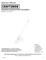
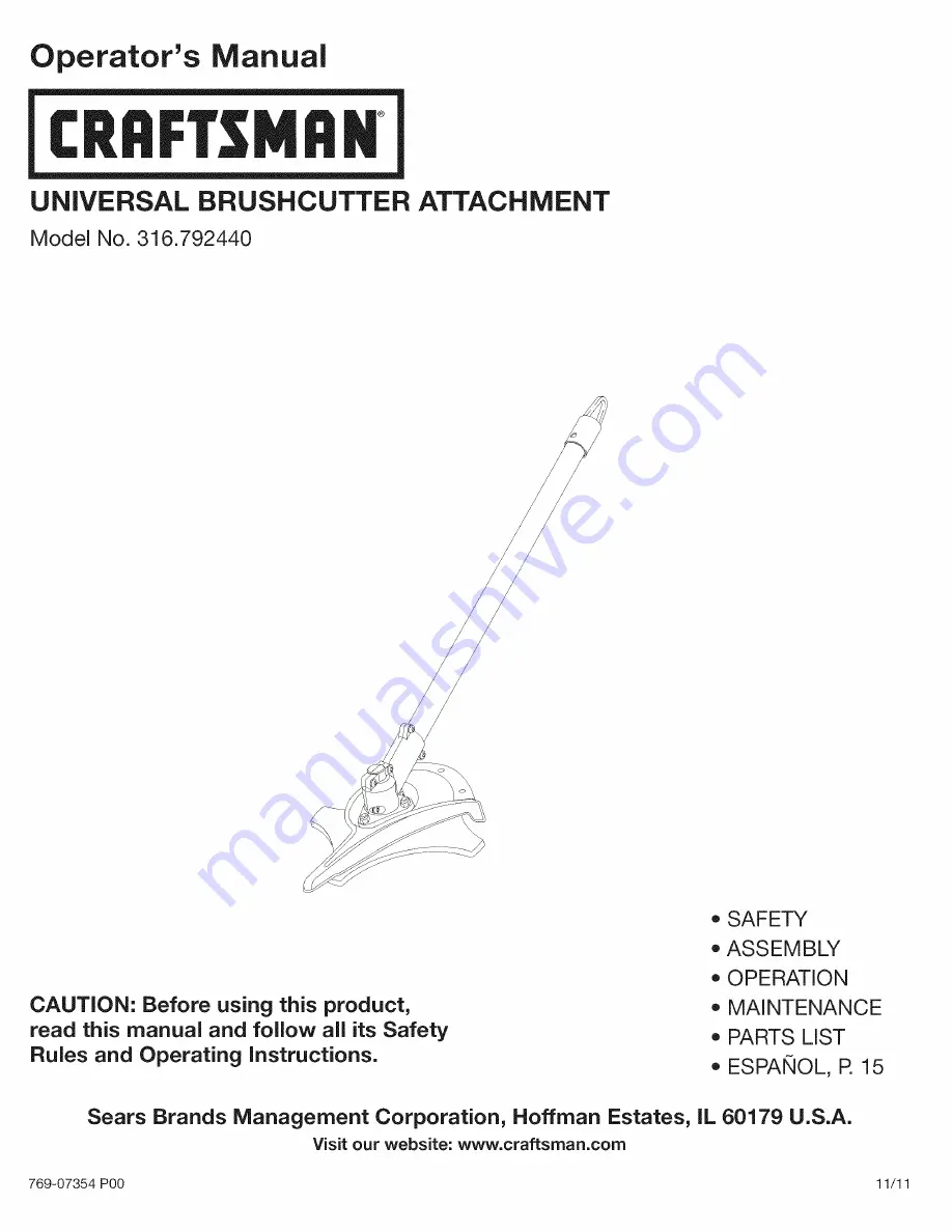
background image

Summary of Contents for 316.792440

Page 1: ...re using this product read this manual and follow all its Safety Rules and Operating instructions SAFETY o ASSEMBLY OPERATION MAINTENANCE PARTS LIST ESPANOL R 15 Sears Brands Management Corporation Hoffman Estates IL 60179 U S A Visit our website www craftsrnan corn 769 07354 P00 11 11 ...

Page 2: ...emselves eliminate anydanger The instructions orwarnings they give arenotsubstitutes forproper accident prevention measures SYMBOL MEANING DANGER Signals an EXTREME hazard Failure to obey a safety DANGER signal WILL result in serious injury or death to yourself or to others WARNING Signals a SERIOUS hazard Failure to obey a safety WARNING signal CAN result in serious injury to yourself or to other...

Page 3: ...es and a long sleeve shirt Do not wear loose clothing jewelry short pants sandals or go barefoot Secure hair above shoulder level Make sure the attachment is not in contact with anything before starting the unit Use the unit only in daylight or good artificial light Use the right tool Only use this tool for its intended purpose Always hold the unit with both hands when operating Keep a firm grip o...

Page 4: ...causing injury Keep away from the rotating rotor _ b KEEP BYSTANDERS AWAY _I_ WARNING Keep all bystanders especially children _ and pets at least 50 feet 15 m from the operating area _ TRIMMER BRUSHCUTTER SAFETY WARNING Thrown objects and rotating cutter can i cause severe injury Keep bystanders especially _ _ hildren and pets at least 50 feet 15 m away from the cutting area The cutting attachment...

Page 5: ...Small Crescent Wrench Shoulder Harness 24 in J Handle Assembly w Hardware Gearbox Blade Shield Locking Rod Approximate Unit Weight attachment only 3 75 Ibs 1 7 kg Cutting Path Diameter Cutting Blade 8 in 204 mm Shoulder Harness single quick snap All specifications are based on the latest product information available at the time of printing We reserve the right to make changes at any time without ...

Page 6: ...o the underside of the shaft housing about 7 8 from the shaft grip Fig 1 3 Place the J handle between the top and middle clamp pieces Fig 1 4 While holding the three pieces together install the four 4 screws through the top clamp and into middle clamp NOTE The holes in the top and middle clamp will line up only when assembled correctly 5 Place the clamps and J handle the over the shaft housing and...

Page 7: ...r harness clip 1 Remove the bolt nut and washer that were installed on the harness loop for shipping Keep them handy 2 Pull the clamp open and push it onto the boom 3 Arrange the clip so that it is close to the shaft grip and away from the J handle Fig 4 4 Insert the bolt through the clip and secure it with the washer and nut using a pair of pliers and a small crescent wrench iNSTALL THE SHOULDER ...

Page 8: ...y tightened For decorative edging with the line head trimmer attachment lock the release button of the attachment into the 90 hole Fig 8 Removing the Attachment 1 Turn the knob counterclockwise to loosen Fig 8 2 Press and hold the release button Fig 9 3 While firmly holding the upper shaft housing pull the attachment straight out of the Convertible TM coupler Fig 10 The Convertible TM Coupler Syst...

Page 9: ... warning if the blade snags stalls or binds This is more likely to occur in areas where it is difficult to see the material being cut Cut while swinging the upper body from left to right Maneuver the unit in the opposite direction as the blade spins which increases the cutting action After the return swing move forward to the next area to be cut plant feet again Always release the throttle trigger...

Page 10: ...mains hot for a short time even after the unit is turned off Do not touch the gear housing until it has cooled I NOTE To make cutting blade removal and installation easier place the unit on the ground or on a work bench 1 Align the shaft bushing hole with the locking rod slot and insert the locking rod into the bushing hole Fig 13 2 Hold the locking rod in place by grasping it next to the boom of ...

Page 11: ...cket wrench turning the nut until the blade retainer is snug against the shaft bushing Make sure that the blade is installed correctly then rotate the nut an additional 1 4 to 1 2 turn counterclockwise Fig 17 6 Remove the locking rod from the locking rod slot j _ _WARNING To avoid serious personal injury or damage to the unit do not start or operate this unit with the locking rod in the locking ro...

Page 12: ... Storage 1 2 weeks 1 Store the unit in a horizontal position If this is not possible store the unit vertically with the engine at the top Long term Storage 1 Remove the fuel cap tip the unit and drain the fuel into an approved container 2 Start the engine and allow it to run until it stalls This ensures that all fuel has been drained from the carburetor 3 Allow the engine to cool Remove the spark ...

Page 13: ...HELP 13 ...

Page 14: ...tion phone support from a Sears representative Think of us as a talking owner s manual Once you purchase the Repair Protection Agreement a simple phone call is all that it takes for you to schedule service You can call anytime day or night or schedule a service appointment online The Repair Protection Agreement is a risk free purchase If you cancel for any reason during the product warranty period...

Page 15: ...izar este producto lea este manual y siga todas las reglas de seguridad e instrucciones de operaci6n o SEGURIDAD o ENSAMBLAJE o OPERACION o MANTENIMIENTO LISTA DE PIEZAS Sears Brands Management Corporation Hoffman Estates IL 60179 U S A Visite nuestro sitio web www craftsrnan corn 769 07354 P00 11 11 ...

Page 16: ... si ningQn peligro Las instrucciones o advertencias que dan no sustituyen las medidas adecuadas de prevenci6n de accidentes SJMBOLO SlGNIFICADO PELIGRO Indica un peligro EXTREMO El no obedecer una sehal de seguridad de PELIGRO TRAERA COMO CONSECUENClA que usted u otras personas puedan sufrir lesiones graves o la muerte ADVERTENCIA Indica un peligro GRAVE El no obedecer una sehal de ADVERTENClA de ...

Page 17: ... ser fatal Opere esta unidad solamente en un Area exterior bien ventilada 17 AL OPERAR LA UNIDAD Lleve puestas gafas o lentes de seguridad que cumplan las normas ANSI Z87 1 1989 y esten marcados como tales Use siempre protecci6n para los oidos al operar esta unidad Si la operaci6n levanta polvo Ileve puesta una mascara facial o contra el polvo Use pantalones largos y gruesos botas guantes y camisa...

Page 18: ... gafas o lentes de seguddad que cump an a norma ANS Z87 1989 y protecc 6n para los oJd0sl De set necesario use un protector facial comp eto __ __ _ LOS OBJETOS QUE SALEN DESPEDIDOS Y LA _ CUCHILLA GIRATORIA PUEDEN OCASIONAR _ _ LESIONES GRAVES J_ _ ADVERTENCIA Los objetos pequefios pueden ser lanzados a gran velocidad y ocasionar lesiones Mant6ngase alejado del rotor cuando est6 girando t MANTENGA...

Page 19: ...ara montar la manija en J de 24 pulg con hardware Caja de engranajes Protector de la cuchilla VariUa de traba Cuchilla para maJezas Peso aproximado de la unidad s61o el accesorio 3 75 libras 1 7 kg Diametro aproximado del Area de corte cuchilla de corte 8 pulgadas 204 mm Ames de hombro quick snap sola Todas las especificaciones se basan en la informaci6n del producto mas reciente disponible en el ...

Page 20: ...re la abrazadera superior y la abrazadera media Fig 1 4 Mientras sostiene las tres piezas juntas instale los cuatro 4 tornillos a traves de la abrazadera superior en la abrazadera media NOTA Los orificios de la abrazadera superior y media quedaran alineados solamente cuando se ensamble correctamente 5 Coloque las abrazaderas y la manija en J por encima del bastidor del eje y sobre la abrazadera in...

Page 21: ...ara los hombros 1 Quite el pemo la tuerca y la arandela colocadas en el lazo del arnes para su envio Dejelas a mano 2 Tire para abrir la presilla y empQjela sobre el brazo 3 Acomode la presilla de forma tal que quede cerca de la empu_adura del eje y lejos de la manija en J Fig 4 4 Introduzca el perno en la presilla y ajQstelo con la arandela y la tuerca usando una pinza y una Ilave sueca peque_a I...

Page 22: ...retada Para hacer cortes orillados decorativos con el accesorio de corte del cabezal de linea trabe el bot6n de desconexi6n del accesorio en el interior del orificio de 90 Fig 8 C6mo quitar el accesorio 1 Para aflojar gire la perilla en sentido contrario alas agujas del reloj Fig 8 2 Oprima y sostenga el bot6n de desconexi6n Fig 9 3 A la vez que sujeta firmemente la caja del eje superior saque el ...

Page 23: ...iolento para ocasionar que la unidad y o el operador sean lanzados en cualquier direcci6n y que posiblemente se pierda el control de la unidad El empuje de la cuchilla puede producirse sin aviso si la cuchilla se desbasta se atasca o se dobla Esto es mas probable que en Areas en las que es dificil ver el material que se esta cortando Corte moviendo el torso de izquierda a derecha Maniobre la unida...

Page 24: ...terial seenrede enla cuchilla siga estos pasos Corte con elregulador almaximo Introduzca launidad enelmaterial acortar balanceandola de izquierda aderecha Fig 12 Evite cortar elmaterial durante elbalanceo para volver ala posici6n inicial Fig 12 24 ...

Page 25: ...iones al operador El bastidor se mantiene caliente durante un breve lapso de tiempo aOn despues de apagada la unidad No toque el bastidor del engranaje hasta que se haya enfriado Para facilitar la remoci6n y la instalaci6n coloque la unidad sobre el suelo o sobre un banco de taller Alinee el orificio del buje del eje con la ranura de la varilla de traba e inserte la varilla de traba en el orificio...

Page 26: ...13mm ygire latuerca hasta que elreten de lacuchilla quede ajustado contra elbuje deleje AsegOrese de que lacuchilla este bien instalada luego girelatuerca 1 4 o1 2 vuelta mas ensentido contrario alasagujas delreloj Fig 17 6 Quite lavarilla detraba delaranura correspondiente 1 4 a _ 2vuelta en sentJdo contrario a las agujas del reloj Fig 17 _ ADVERTENClA Para evitar lesiones personales graves I o d...

Page 27: ...los nitros Alrnacenamiento pot corto tiempo 1 a 2 semanas 1 Guarde la unidad en posici6n horizontal Si no es posible guarde la unidad en posici6n vertical con el motor para arriba Alrnacenamiento a largo plazo 1 Quitele la tapa al tanque de combustible incline la unidad y vacie el combustible en un contenedor aprobado 2 Arranque el motor y dejelo funcionar hasta que se cale Con esto se asegura vac...

Page 28: ...28 ...

Page 29: ... telefono de un representante de Sears Considerenos un manual de usuario que habla Una vez que adquiera el Convenio de Protecci6n de Reparaci6n todo Io que necesita es hacer una simple Ilamada para programar el servicio Puede Ilamar a cualquier hora del dia o de la noche o programar el servicio pot Internet El Convenio de Protecci6n de Reparaci6n es una compra libre de riesgo Si usted Io cancela p...

Page 30: ...30 ...

Page 31: ...791 613226 791 682075B 791 180194 791 612605 Description Lower Drive Shaft Housing Assembly Lower Flexible Drive Shaft Shield Mount Screw Assembly 2 piece Gearbox Assembly includes 5 6 Gearbox Mounting Hardware Anti Rotation Screw Blade Driver Palnut Blade Shield Shield Mount 4 Tooth Blade Retaining Washer Nut J Handle Assembly Handle Bracket Assembly includes 15 18 Screw Upper Handle Clamp Middle...

Page 32: ...y in items like vacuums lawn equipment and electronics call anytime for the location of your nearest Sears Parts Repair Service Center 1 800 488 1222 U S A 1 800 469 4663 Canada www sears corn www sears ca To purchase a protection agreement on a product serviced by Sears 1 800 827 6655 U S A 1 800 361 6665 Canada Para pedir servicio de reparaci6n a domicilio y para ordenar piezas 1 888 SU HOGAR 1 ...

Reviews: