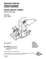
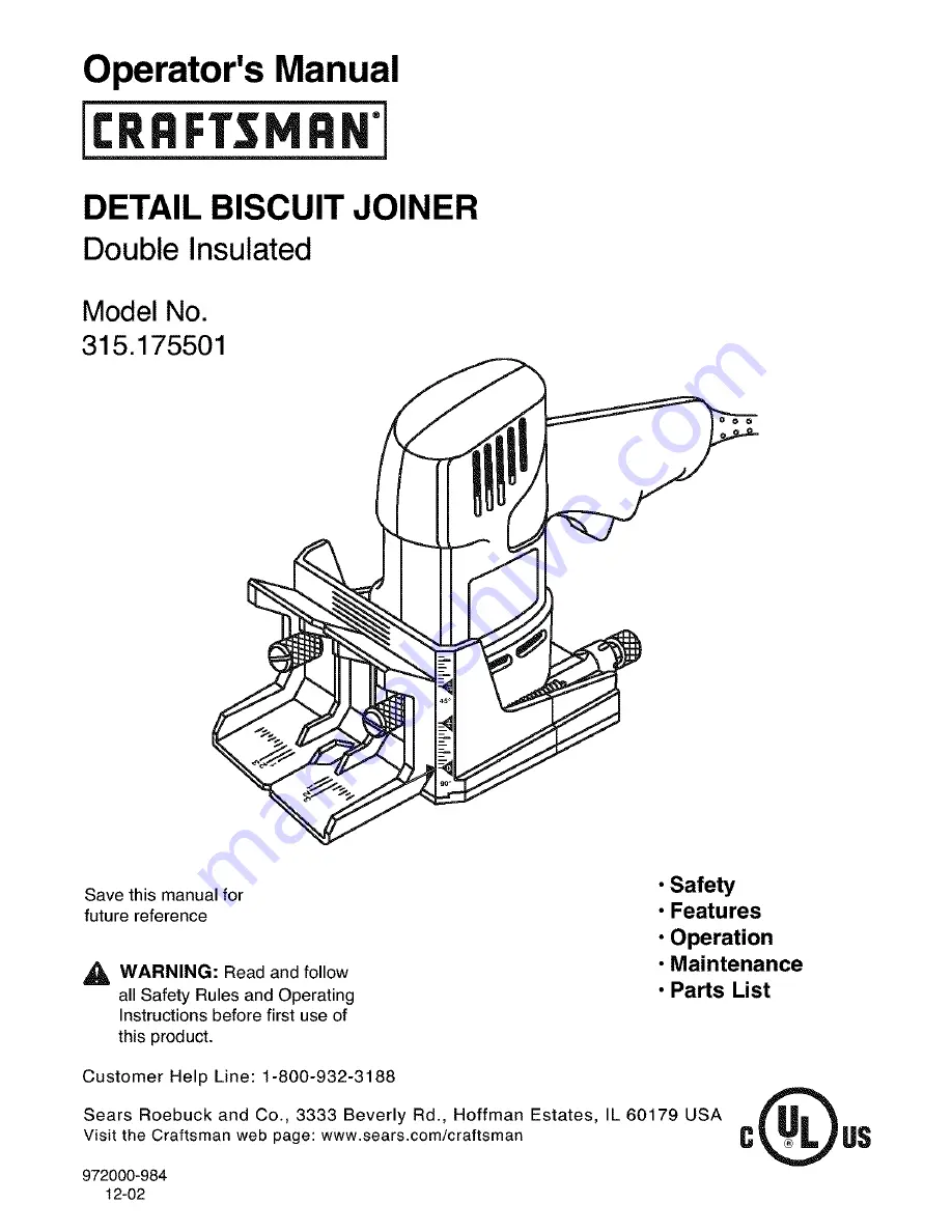
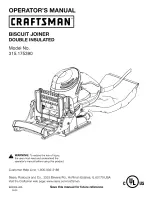
Craftsman 315.175501, Operator'S Manual
The Craftsman 315.175501 Operator's Manual is a versatile and reliable resource for mastering the functionality of your power tool. This comprehensive manual provides step-by-step instructions and safety tips for optimum performance. Download it for free from manualshive.com to unlock the full potential of your Craftsman 315.175501!
Share
Download


Reviews:
No comments
Related manuals for 315.175501

RF100/710
Brand: Felisatti Pages: 53
EBJ720K
Brand: Ryobi Pages: 24
054-8106-4
Brand: MasterCraft Pages: 12

BBJ9000
Brand: BorMann Pages: 25
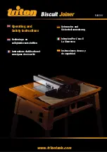
BJA 300
Brand: Triton Pages: 9

Top 21
Brand: Lamello Pages: 120
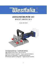
96 30 49
Brand: Westfalia Pages: 28
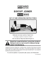
38648
Brand: Chicago Electric Pages: 14
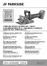
PFDFA 20-Li A1
Brand: Parkside Pages: 179
17539 - 6.0 Amp Plate Jointer
Brand: Craftsman Pages: 26

DW682K
Brand: DeWalt Pages: 64
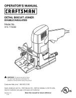
17550 - 3.5 Amp Detail Biscuit Jointer
Brand: Craftsman Pages: 26
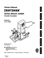
315.175500
Brand: Craftsman Pages: 24

BM018
Brand: 909 Pages: 16
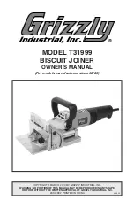
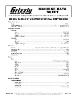
T31999
Brand: Grizzly Pages: 32
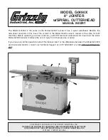
G0490X
Brand: Grizzly Pages: 2
G0490
Brand: Grizzly Pages: 68
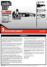
BJK-1010U
Brand: Ozito Pages: 10


